In case of Infrared communication, there is a line of sight connection between the transmitter and receiver but Communication over Radio Frequency does not have line of sight connection. The range of RF communication is very high when compared to IR communication. In this article, we understand, what is RF transmitter and Receiver. Also, we will discuss about its features and applications.
What is RF Module?
As the name suggests, RF module operates at Radio Frequency. This frequency range varies between 30 kHz & 300 GHz. In this RF system, the digital data is represented as variations in the amplitude of carrier wave. This types of modulation is an Amplitude Shift Keying (ASK) .

This RF module is a combination of RF Transmitter and RF Receiver. The transmitter/receiver (Tx/Rx) pair operates at a frequency of 433 MHz.
The RF transmitter receives serial data and transmits it wirelessly through through its RF antenna. The transmission occurs at the rate of 1 Kbps – 10 Kbps. RF receiver receives the transmitted data and it is operating at the same frequency as that of the transmitter.
Features of RF Module:
- The Receiver frequency 433MHz
- Receiver typical frequency 105 Dbm
- Receiver supply current 3.5 mA
- Low power consumption
- operating voltage of receiver is 5V
- The transmitter frequency range 433.92MHz
- Supply voltage of transmitter is between 3V to 6V
- Output power of transmitter is between 4Dbm to 12Dbm
433 MHz RF Transmitter and Receiver:
In many projects, we use RF modules to transmitting and receiving the data because it has a high volume of applications than IR. RF transceiver module will always work in a pair that is it needs a Transmitter and Receiver to send and receive the data. A transmitter can only send information and a Receiver and can only receive it, so data can send from one end to another and not the other way around.

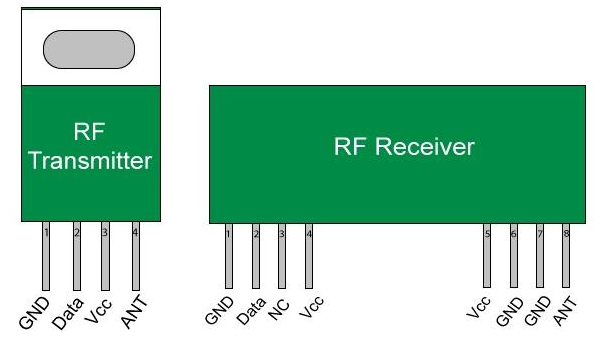
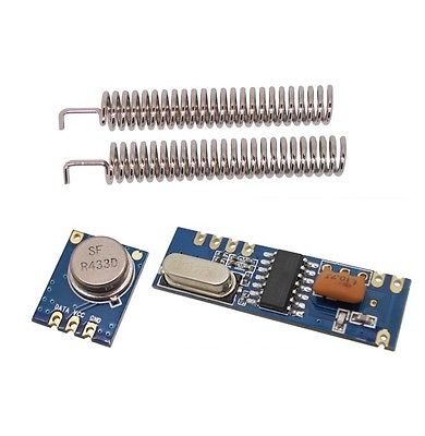
The Transmitter module consists of three pins namely Vcc, Din and ground as shown above. The Vcc pin has a wide range input voltage from 3V to 12V. The transmitter consumes a minimum current of 9mA and can go as high as 40mA during transmission. The center pin is the data pin to transmite the signal. This signal modulated using the ASK and then sent on air at a frequency of 433MHz.
RF receiver module has four pins namely Vcc, Dout, Linear out and Ground as shown above. The Vcc pin should be powered with a regulated 5V supply. The operating current of this module is less than 5.5mA. The pins Dout and Linear out is shorted together to receive the 433Mhz signal from air. This signal is then demodulated to get the data and sent out through the data pin.
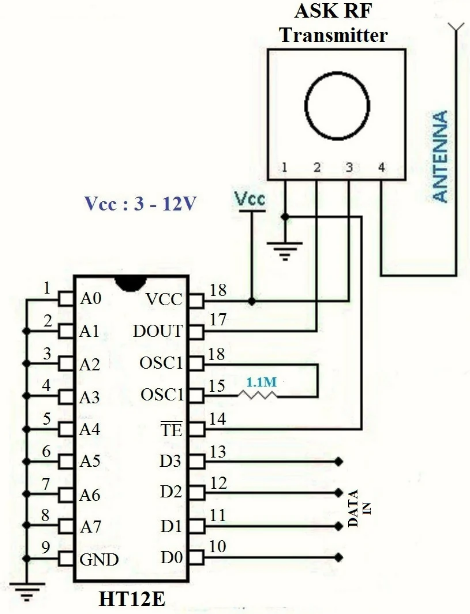
RF Transmitter Circuit Diagram

HT12E is an encoder IC that converts the 4-bit parallel data from the 4 data pins into serial data in order to transmit over RF link using transmitter.
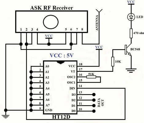
RF Receiver Circuit Diagram

HT12D is a decoder IC that converts the serial data received by the RF Receiver into 4-bit parallel data and drives the output accordingly.
Why Encoders and Decoders are Necessary?
The RF modules can also function without the need of Encoder and Decoder modules. Simply power on both the modules with the corresponding voltage mentioned above. But, there is a big drawback in this method. You can have only one button on the sender side and one output on the receiver side. So to have more inputs and outputs, the encoder and decoder modules are required.
The HT12D and HT12E are 4-data bit encoder and decoder modules. This means that we can make (2^4 = 16) 16 different combinations of inputs and outputs. These are 18 pin IC’s which can operate between 3V to 12V input power supply. As said they have 4-data bit and 8-addresss bit, these 8 address bits has to be set same on both the encoder and decoder to make them work as a pair.
Applications of RF Module
- Vehicle monitoring
- Remote control
- Telemetry
- Small-range wireless network
- Wireless meter reading
- Access control systems
- Wireless home security systems
- Area paging
- Industrial data acquisition system
- Radio tags reading
- RF contactless smart cards
- Wireless data terminals
- Wireless fire protection systems
- Biological signal acquisition
- Hydrological and meteorological monitoring
- Robot remote control
- Wireless data transmissions
- Digital video/audio transmission
- Digital home automation, such as remote light/switch
- Industrial remote control, telemetry and remote sensing
- Alarm systems and wireless transmission for various types of low-rate digital signal
- Remote control for various types of household appliances and electronics projects
- Many other applications field related to RF wireless controlling
- Mobile web server for elderly people monitoring
Here's a video that explains all of the above points.
Hope this article helps you to understand about the RF transmitter and Receiver. We at Robu.in hope that you found it interesting and that you will come back for more of our educational blogs.


How can I make my radio station
Dear sir..
This is Manjula, who is a science teacher. My student recently got selected to national level in science exhibition, where she explained rc controlled water life jacket. Your article on rf module has really helped a lot.
Thank you for useful information.