What is Dual Power Supply? – Circuit Construction and Working
A Dual power supply is a regular direct current power supply. It can provide a positive as well as negative voltage. It ensures stable power supply to the device as well as it helps to prevent system damage.

Many electronic circuits require a source of DC power. A dual power supply is used to power the electronic as well as electrical equipment. The dual power supply provides positive as well as negative potential with the ground. Mainly electronic circuits consist of tubes or transistors, require a DC power source.
For example, in tube amplifiers, DC voltage was needed for the plate, screen grid, and control grid. Similarly, DC is needed in emitter and collector bias in transistors. Also, Op-Amps need dual power sources. In such cases, batteries are rarely used as they are costly and require frequent replacement.
In this chapter, we would be discussing circuit construction and the working of dual power supply.
Why We Need Dual Power Supply?
1. The need for a Dual power supply in OPAMPS
OPAMPS generally need to swing bipolar output voltages. One of them goes either in positive or in negative in response to the normal input signal range. Thus OPAMPS has two rails. So in order to provide power to the OPAMPS, we need a Dual power supply.
2. The need for a Dual power supply in Generators
When we want to run two different power circuits on the same power supply without taking it offline, we need a dual power supply. It allows us to perform maintenance and other work on electrical equipment without taking the device offline.
3. The need for a Dual power supply in DIY
In DIY, we can use a dual power supply as a cell phone charging circuit, power bank circuit, in the Battery-less power circuits, also in case of any direct current power supply, we can use this Dual power supply.
Types of Dual Power Supply
Most electronic equipment requires a DC power source in the range of 5-15V. Therefore, there are three types of dual power supply.
- 5 Volt Dual power supply circuit
- 12 Volt Dual power supply circuit
- 15 Volt Dual power supply circuit
All these circuits have individual step-down transformers and voltage regulators. We can add LED for indication purposes if needed.
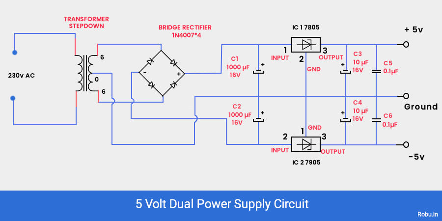
5V Dual Power Supply
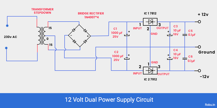
12V Dual Power Supply
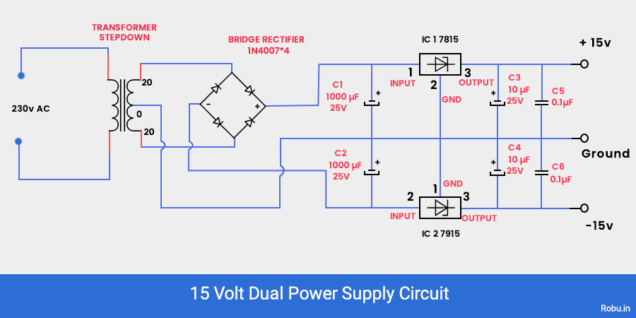
15V Dual Power Supply
Components Required
- Step down buck converter
- Capacitors
- The voltage regulator 7805, 7812, 7905, 7912
- Resistor
- LED
- Printed board
- Buck strip
- Dupont Cables
Construction And Working
Construction
- Connect four diodes as shown in the figure to form a rectifier circuit.
- The input of this rectifier should be connected to the secondary winding of the transformer while the output is connected to the voltage regulator IC.
- An input terminal of the voltage regulator is connected to the ground through a 1000µF capacitor.
- The output of these voltage regulators is our final output.
- Each reference terminal is connected to the ground directly.
Working:
Basically, any power supply consists of four blocks
- Transformer.
- Rectifier circuit.
- Filter circuit.
- Voltage Regulator.
The input of any power is 230V AC; to step down, we use a step-down transformer. This transformer steps down the 230V AC up to 5V AC.
Now we want DC voltage; the rectifier circuit does this task. The rectifier converts the stepped down AC voltage to the DC voltage.
Once we got DC voltage does not mean the task is complete. To get stabilized DC voltage, we need a filter circuit. The filtering task is done by the capacitors used in the circuit. There are several peaks in the output of the rectifier. Capacitors help us to reduce these peaks, and thus the filtering gets completed.
Now the main and the last task is voltage regulation. To complete this task, we have to use a different voltage regulator IC's. For example, 7812, 7912, Etc. Generally, the 78xx series is for a positive supply, and 79xx is for a negative supply.
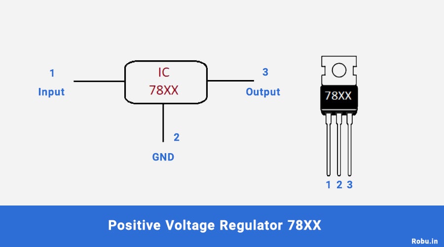
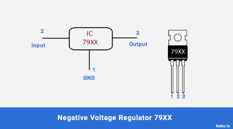
By using such integrated circuits we can control the voltage significantly.
Voltage Regulator IC (78xx) (79xx)
78xx
The voltage regulator IC 78xx is also referred to as L78xx, LM78xx, or MC78xx. When we have to supply a specific amount of voltage to a piece of equipment, the 78xx series is the suitable IC we can use. It operates on a constant voltage and a constant current.
It is the positive voltage regulator. It has an inbuilt internal thermal overload and short circuit current limiting protection circuit. The maximum junction temperature is 125-degree Celcius.
79xx
The 79xx voltage regulators are negative voltage regulators. The negative voltage regulators are as important as the positive ones. These ICs have three terminals and are available in the range of fixed voltages i.e. -5v, -12v, -15v. They also have an inbuilt internal thermal overload and short circuit current limiting protection circuit.
Applications
1.In Audio amplifiers, operational amplifiers, power amplifiers we use a dual power supply.
2. In the low voltage direction of the DC motor, we can use this dual power supply.
3.In 12V battery charging circuit.
4.In a cell phone charging circuit.
5.In a power bank circuit.
Final Words
Thank you for being with me till the end. Hope your all concepts about the power supply got cleared.
If you like this article let me know in the comment section. Also, feel free to give suggestions and share your experience while doing this experiment in the comment section.


