Boost Your DIY Project: Built a Stunning Digital Clock with Seeed Studio XIAO ESP32S3, OLED Display, and NTP Accuracy
In this project we are going to use Seeed Studio XIAO ESP32S3, OLED display and NTP to make Micro digital desk clock. This clock will be connected to Wi-Fi and
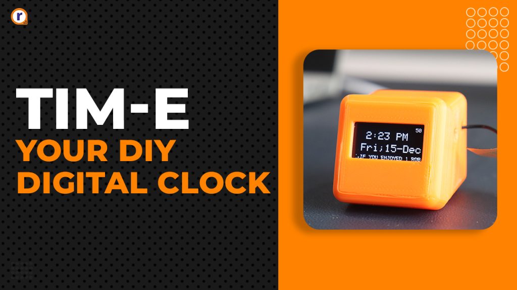
In this project we are going to use Seeed Studio XIAO ESP32S3, OLED display and NTP to make Micro digital desk clock. This clock will be connected to Wi-Fi and take real time date and time by using NPT.
In this desk clock we do not require RTC module, this can also be used as alarm clock
So, let’s create
Let's start with
What is Seeed Studio XIAO ESP32S3& why do you we use it?
SEED Studio XIAO: SEEED Studio manufactures a line of compact and reasonably priced development boards known as the XIAO. These boards include a microcontroller, often an ARM Cortex-M0 or M4, depending on the model, and are intended for projects needing a small form factor.
ESP32 S3: Espressif Systems developed the ESP32 S3 microcontroller chip. Many IoT (Internet of Things) applications can benefit from the ESP32 series' well-known Wi-Fi and Bluetooth features. Most likely, the "S3" designates a particular ESP32 series variation or version.
Why make use of it?
Compact Size: Because of its tiny form factor, the XIAO is a good choice for applications that need to be portable or have a restricted amount of area.
Features of ESP32: The ESP32 S3, a member of the ESP32 series, has Bluetooth and Wi-Fi connection, which makes it appropriate for Internet of Things applications where wireless communication is crucial.
Community and Support: There are robust communities for Espressif Systems and SEEED Studio that offer documentation, support, and a variety of libraries to make development easier.
Affordability: Since XIAO boards are frequently reasonably priced, amateurs, students, and developers working on side projects can use them.
I advise you to review the Seeed Studio XIAO ESP32 S3 specific documentation before beginning your project to make sure you have the most recent and accurate information regarding its features and capabilities.
Table of content
- Hardware requirement
- Software requirement
- Circuit diagram
- Adding Compatible Board and Libraries
- Code
- Breadboard test connections
- How to simply 3D print
- Hardware interfacing
- Final working of project
- Conclusion
Hardware requirement of this project
- Seeed Studio XIAO ESP32 S3
- 0.96 Inch OLED Display Module
- LED
- Breadboard
- Jumper Wire
- 3D printed case
- USB TYPE –C data cable
Software requirement of this project
- Arduino IDE
Circuit Diagram
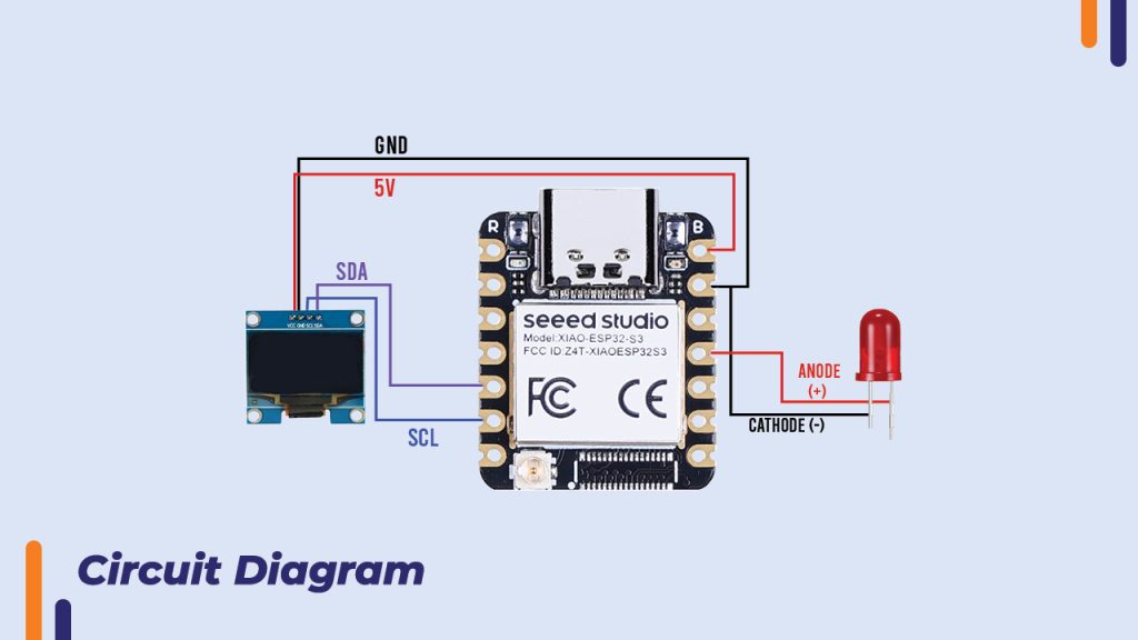
Interface the components as per circuit diagram

Breadboard interfacing and connections
- Make the connection on breadboard as per circuit diagram for testing and connect SEED studio XIAO ESP32 S3 board with you PC or laptop
- Upload the basic Example code for OLED display to check the interfacing of OLED display with board
Board Setup in IDE and port selection
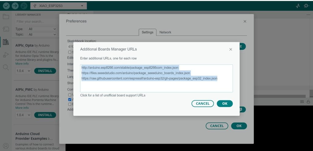
Add the given boards in addition board
Files>Preferences>Paste below URL in ->Additional boards URLs>ok
http://arduino.esp8266.com/stable/package_esp8266com_index.json
https://files.seeedstudio.com/arduino/package_seeeduino_boards_index.json
https://raw.githubusercontent.com/espressif/arduino-esp32/gh-pages/package_esp32_index.json
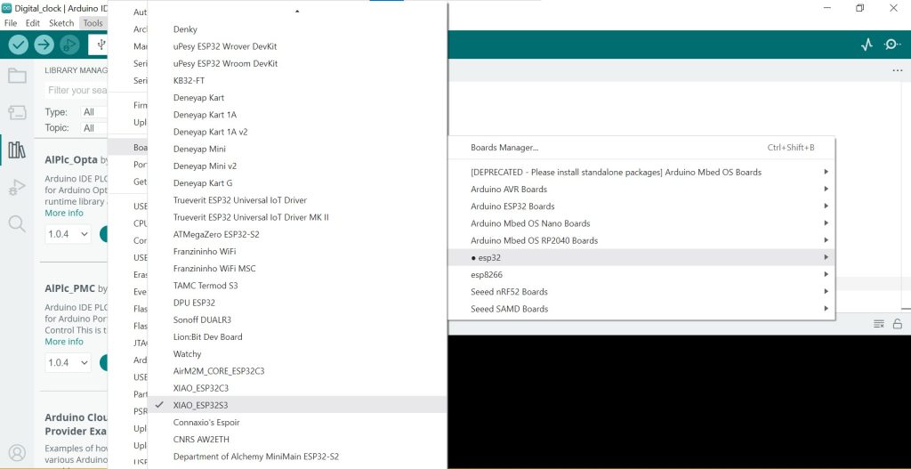
Select proper board with proper model and COM port for Uploading code
Tools->Board->esp32->XIAO_ESP32S3
For Port
Tools->Port->select the COM PORT associated with ->Board
Libraries Installation
Just check Libraries in code are installed or not if not install them accordingly
Install the OLED and ESP32 libraries that are required. The following libraries can be installed using the Arduino Library Manager:
Adafruit GFX Library for ESP32
Adafruit SSD1306

CODE
#include <Wire.h>
#include <Adafruit_GFX.h>
#include <Adafruit_SSD1306.h>

#include <WiFi.h>
#include <NTPClient.h>
#include <WiFiUdp.h>

#define SCREEN_WIDTH 128
#define SCREEN_HEIGHT 64
#define OLED_RESET -1
#define SCREEN_ADDRESS 0x3C

Adafruit_SSD1306 display(SCREEN_WIDTH, SCREEN_HEIGHT, &Wire, OLED_RESET);

const char *ssid = "ROBU_TEST";//SET UP YOUR Wi-Fi NAME
const char *password = "12345678";//SET UP YOUR Wi-Fi PASSWORD

WiFiUDP ntpUDP;
NTPClient timeClient(ntpUDP, "pool.ntp.org");

String weekDays[7] = {"Sun", "Mon", "Tue", "Wed", "Thu", "Fri", "Sat"};
String months[12] = {"Jan", "Feb", "Mar", "Apr", "May", "Jun", "Jul", "Aug", "Sep", "Oct", "Nov", "Dec"};

const int ledPin = D10;   // Change this to your actual LED pin number on the Xiao ESP32 S3
const int buzzerPin = D9; // Change this to your actual buzzer pin number on the Xiao ESP32 S3

// Define the desired LED activation and deactivation times
const int activateHour = 10;    // Set your activation hour (in 24 Hour Format)
const int activateMinute = 38;  // Set your activation minute
const int deactivateHour = 10;  // Set your deactivation hour (in 24 Hour Format)
const int deactivateMinute = 39; // Set your deactivation minute

char intro[]= "GIVE THIS VIDEO A LIKE,IF YOU ENJOYED | ROBU.IN";
int x, minX;

bool deviceActive = false;

void wifiConnect() {
  display.setTextSize(2);
  display.setTextColor(SSD1306_WHITE);
  display.clearDisplay();
  display.setCursor(0, 10);
  display.println("WiFi");
  display.setCursor(0, 30);
  display.println("Connecting");
  display.display();

  WiFi.begin(ssid, password);
  while (WiFi.status() != WL_CONNECTED) {
    delay(1000);
  }
  display.setTextSize(2);
  display.setTextColor(SSD1306_WHITE);
  display.clearDisplay();
  display.setCursor(0, 10);
  display.println("WiFi");
  display.setCursor(0, 30);
  display.println("Connected");
  display.display();
  delay(2000);
}

void clockDisplay() {
  timeClient.update();
  int currentHour = timeClient.getHours();
  int currentMinute = timeClient.getMinutes();
  int currentSecond = timeClient.getSeconds();
  String am_pm = (currentHour < 12) ? "AM" : "PM";
  if (currentHour == 0) {
    currentHour = 12; // 12 AM
  } else if (currentHour > 12) {
    currentHour -= 12;
  }

  String weekDay = weekDays[timeClient.getDay()];
  time_t epochTime = timeClient.getEpochTime();
  struct tm *ptm = gmtime(&epochTime);
  int monthDay = ptm->tm_mday;
  int currentMonth = ptm->tm_mon + 1;
  String currentMonthName = months[currentMonth - 1];
  int currentYear = ptm->tm_year + 1900;

  display.clearDisplay();
  display.setTextSize(2);
  display.setTextColor(SSD1306_WHITE);
  display.setCursor(18, 10);
  display.print(String(currentHour) + ":" + String(currentMinute) + " " + am_pm);
   display.setTextSize(2);
  display.setCursor(9, 33);
  display.println(String(weekDay) + ";" + String(monthDay) + "-" + String(currentMonthName));//+"-"+String(currentYear)

  display.setTextSize(1);
  display.setTextColor(WHITE);
  display.setCursor(115, 0);
  display.print(currentSecond);
}

void textScroll() {
  display.setTextSize(1);
  display.setCursor(x,55);
  display.print(intro);
  x=x-1;
  if(x < minX) x = display.width();
}

void deviceActivation(){
 timeClient.update();
  int currentHour = timeClient.getHours();
  int currentMinute = timeClient.getMinutes();

  if ((currentHour > activateHour || (currentHour == activateHour && currentMinute >= activateMinute)) &&
      (currentHour < deactivateHour || (currentHour == deactivateHour && currentMinute < deactivateMinute))) {
    deviceActive = true;
    digitalWrite(ledPin, HIGH); // Activate LED
  } else {
    deviceActive = false;
    digitalWrite(ledPin, LOW); // Deactivate LED
  }}

void setup() {

  display.begin(SSD1306_SWITCHCAPVCC, SCREEN_ADDRESS);
  display.clearDisplay();
  display.display(); // Initialize and clear the display

  pinMode(ledPin, OUTPUT);     // Initialize the LED pin
  pinMode(buzzerPin, OUTPUT); // Initialize the buzzer pin

  wifiConnect();

  timeClient.begin();
  timeClient.setTimeOffset(19800);

  display.setTextSize(2);
  display.setTextColor(WHITE);
  display.setTextWrap(false);
  x = display.width();
  minX = -6 * strlen(intro);

  timeClient.update();
  int currentHour = timeClient.getHours();
  int currentMinute = timeClient.getMinutes();
  if ((currentHour > activateHour || (currentHour == activateHour && currentMinute >= activateMinute)) &&
  (currentHour < deactivateHour || (currentHour == deactivateHour && currentMinute < deactivateMinute))) {
  deviceActive = true;
  digitalWrite(ledPin, HIGH); // Activate LED
  }}

void loop() {
  clockDisplay();
  textScroll();
  display.display();
  deviceActivation();

  static bool previousDeviceActive = false;
  if (deviceActive != previousDeviceActive) {
  previousDeviceActive = deviceActive;
  digitalWrite(buzzerPin, HIGH); // Activate Buzzer
  delay(1000); // Keep the buzzer on for 1 second
  digitalWrite(buzzerPin, LOW); // Deactivate Buzzer
  }

}
Debugging and Uploading code
- Connect the circuit on breadboard as per circuit diagram.
- Verify and upload the above code into SEED studio XIAO ESP32 S3.
- Make sure your Wi-Fi is on and proper credential is provided in the code.
- Check if Seeed Studio XIAO ESP32S3 board Is connected to Wi-Fi/hotspot
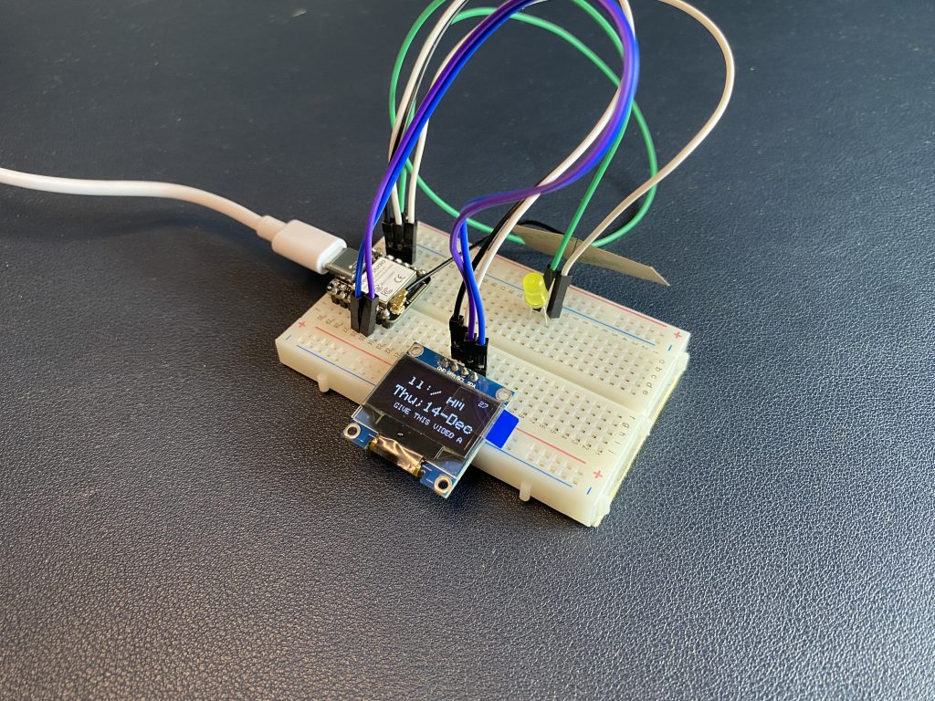
- If connections and code are proper OLED display will start showing current Time and date with Scrolling text and LED will operate on the setup time it can be used to set up specific alarm
Breadboard test result
Breadboard test circuit according to circuit diagram
How to 3D print outer case
Process
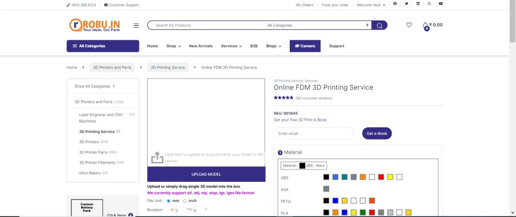
- Visit 3D print site- https://robu.in/product/3d-printing-service/?utm_source=website&utm_medium=header&utm_campaign=3d-printing-service&utm_id=free_promotion
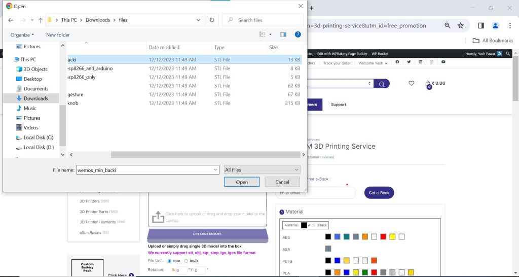
- Download STL files from Given link
- Head- https://robu.in/wp-content/uploads/2023/12/Head.stl
- Base- https://robu.in/wp-content/uploads/2023/12/Base.stl
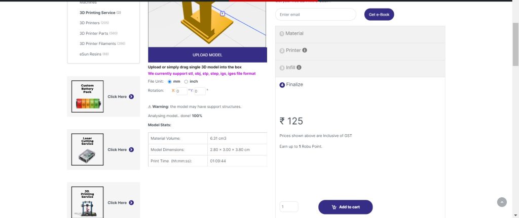
- Click on Upload Model->Select proper STL file from device–>open it
Select the Material ->PLA and color>orange ->NEXT
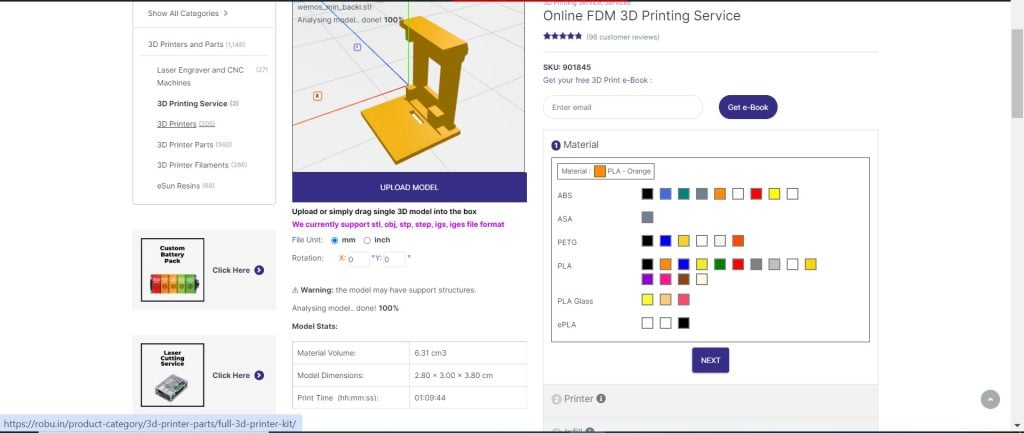
Select printer-> 0.2 mm Standard Quality->NEXT

Select in Fill->20%->NEXT

Finalize printing Cost will show -> Select Quantity -> Add to cart
View cart->Apply coupon if you have->verify the material, cost and quantity->Proceed to checkout->make the payment
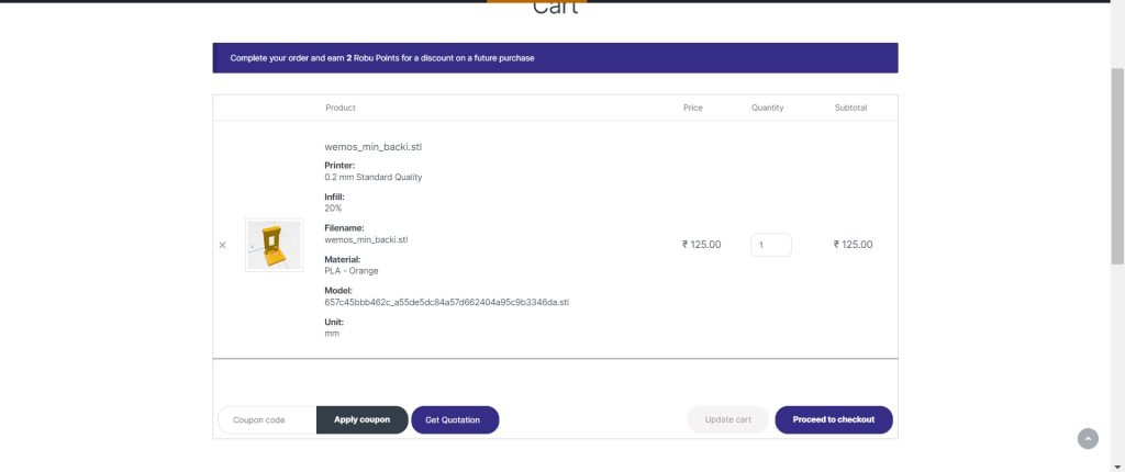
There are two STL file Base and Head follow the same procedure for Head add both print to cart and and make payment
Hardware interfacing
connect the Seeed Studio XIAO ESP32S3 with OLED display using jumper wire and set the OLED display and Seeed Studio XIAO ESP32S3 board into 3D printed case as show in image below


Hardware final test
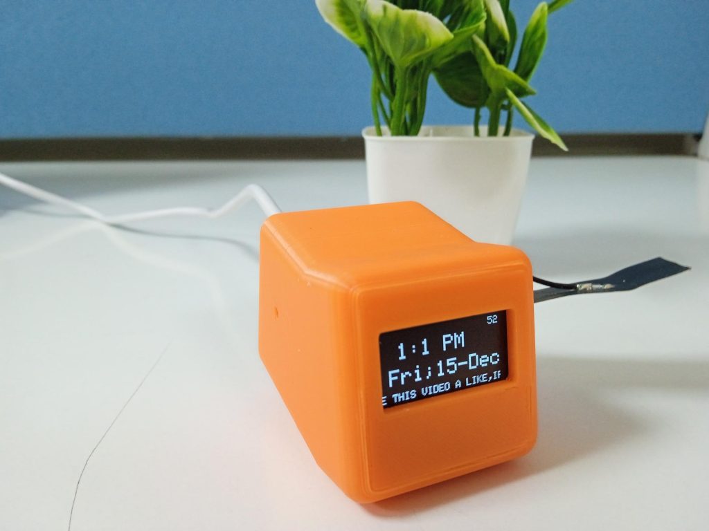
Close the 3D case and plug in the Type-C cable in clock
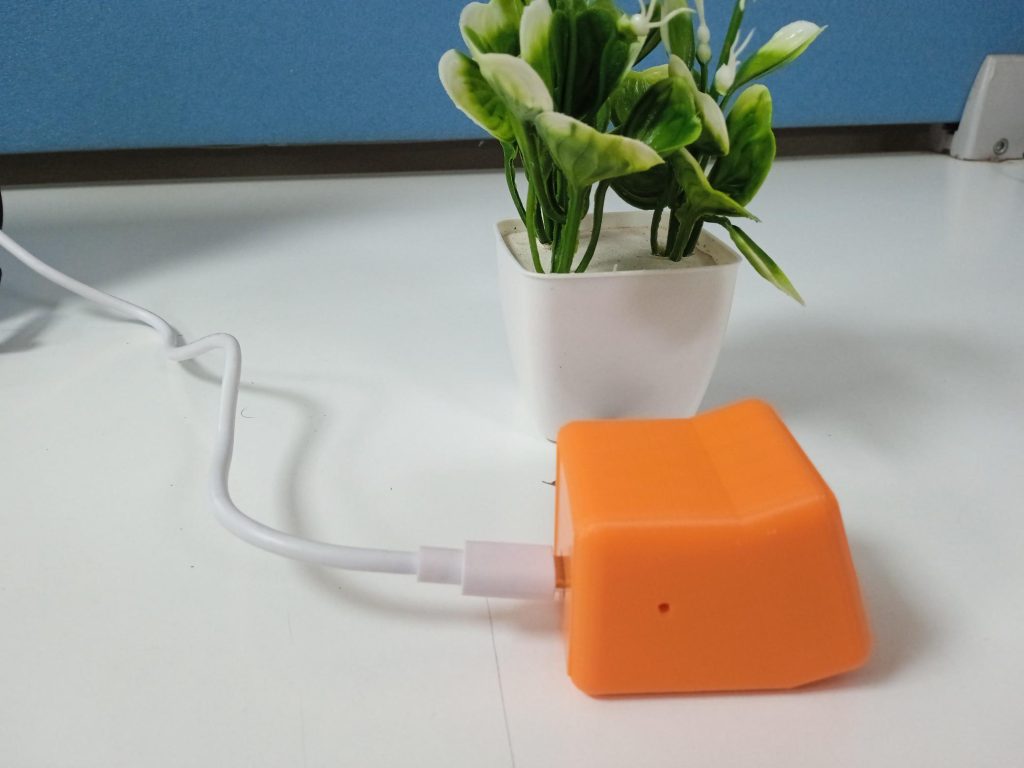

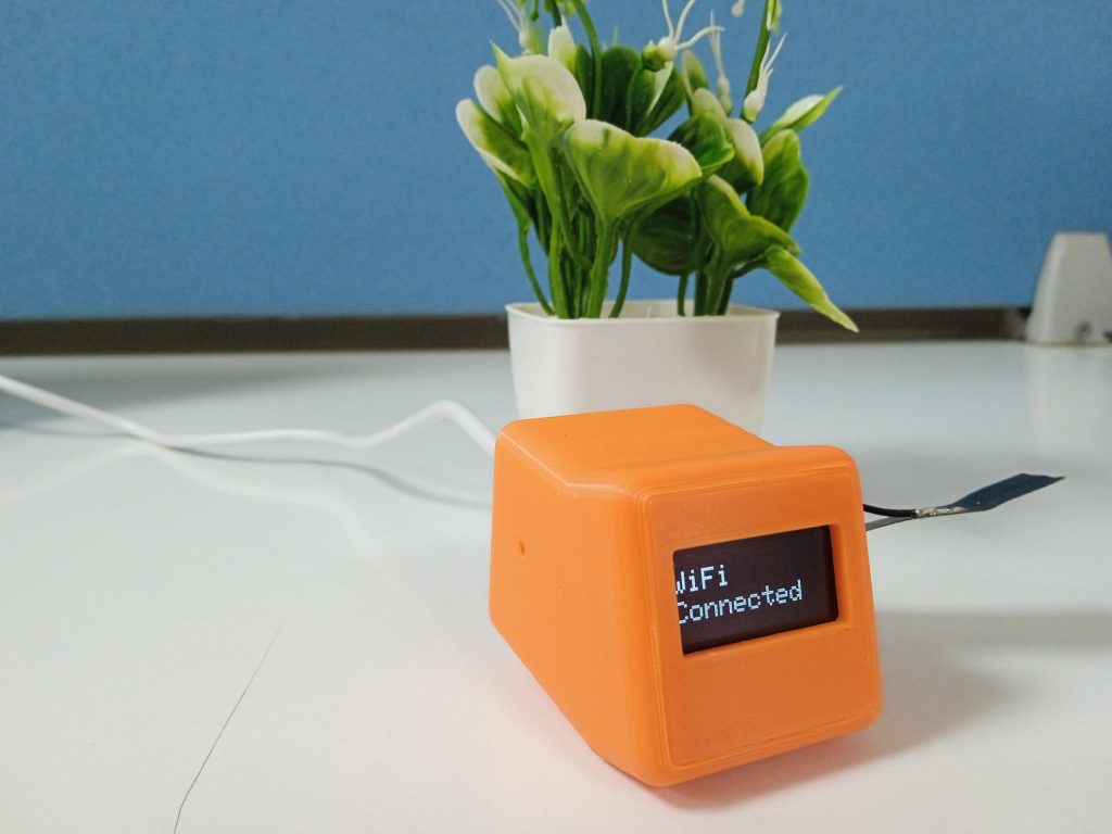
Final working of project
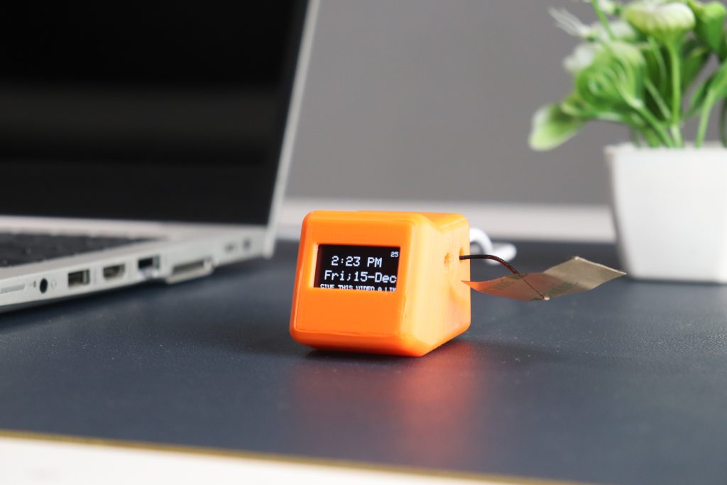
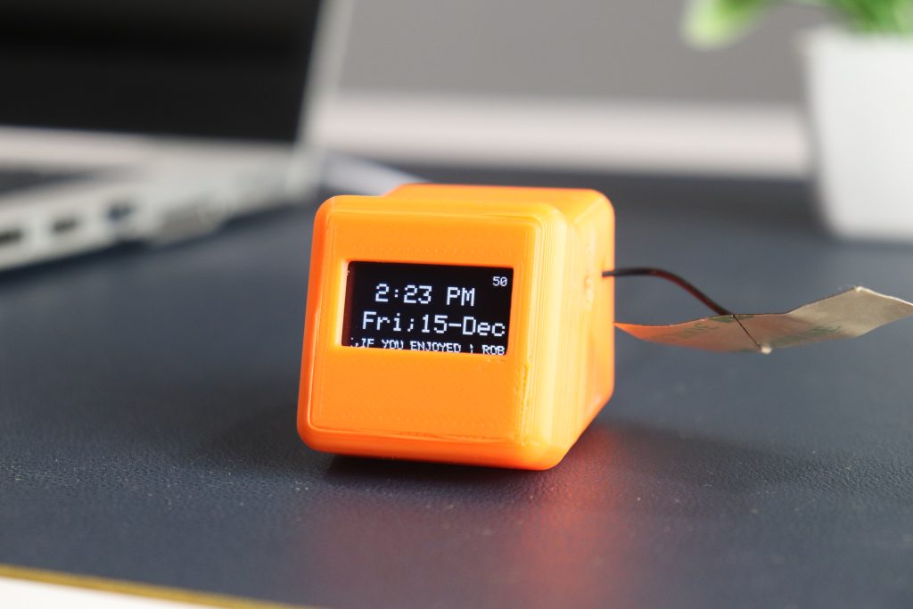
The working of this project is simple we connect OLED display with Seeed Studio XIAO ESP32S3 with the help of NPT Seeed Studio XIAO ESP32S3 board gets real-time date and time and update it to OLED display just we must verify that it is connected to Wi-Fi it will start displaying date time & scrolling text
Conclusion:
In this way we have completed the Digital clock project using Seeed Studio XIAO ESP32S3, OLED display and NTP. Seeed Studio XIAO ESP32S3 Digital clock shows time using NPT & does not require external RTC module it Automatically connects to your Wi-Fi and shows you real-time date & time. It does not require battery or cell to operate it takes supply from USB cable, so chances of power failure are low.
Related post:
Getting Started with Arduino IoT Cloud: Exchanging Data Between the Cloud and Nano ESP32
ESP32 temperature sensor tutorial: How to Stream real-time data to ThingSpeak
For more interesting projects check out our YouTube channel.



Informative Blog