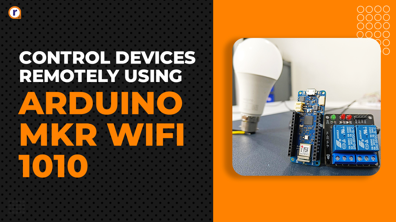
The Basics of Optocoupler Relay
The article will cover the basics of relay along with the basics of optocoupler relay.

We have all heard of the term relay in our life at one point or another. So, what is a relay? What is it used for? What are its types? In this article, we will get to know about all of the above questions. But, more specifically about the optocoupler relay?
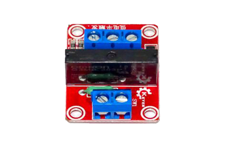
So what is an Optocoupler Relay? A relay operating on the principle of opto-isolation, i.e. there is no direct or hardwire connection between the controller and the relay. And because there is no hardwire, the controller will remain protected against the high voltages that might harm the controller.
Now, coming to the actual optocoupler relay, let's get started with the parts used in an optocoupler relay.
Parts used -
1) Relay
2) Opto-isolator
1) Relay-
Relay is an electronically operated switch. Its three terminals are NC, NO, COM. When the relay coil is not activated, the relay will act as an open circuit, when we activate the relay coil, it will act as a closed circuit.
Relays can be also used as a protecting device, e.g Buchholz relay. It is an oil and gas actuated relay that is used to protect the transformer from the short circuit. When there is a fault in the transformer, due to fault current, the gas in the transformer gets hot and the bubbles will occur and which is given by the chamber pipes to the relay and the alarm circuit will be triggered based on the intensity of the defect.
1.1) Relay pinout and Construction-
1) NO (Normally open)
2) NC (Normally closed)
3) Common terminal
A Relay has an electromagnet, armature (movable contact or COM terminal) and two fixed contacts (NC, NO). In the initial stage, the COM terminal will be close to the NO terminal. When we activate electromagnet, electromagnet generates magnetic flux which attracts armature towards it and the position of the armature changes from the COM to the NC.
1.2) Normally Close-
This is a normally closed connection when the electromagnet is energized, the flux produced by the electromagnet will attract the armature towards the NC terminal. As shown in the second figure.
1.3) Normally Open-
This is a Normally Open connection when the electromagnet is not activated, then the armature will be close to this terminal.
1.4) Application-
- To control the high power devices relays are used.
- In Ac motor's stator, it is used to star connection to delta connection.
1.5) Solid-State relay-
A solid-state relay is another type of relay. It uses thyristor and a transistor to switch output; the switching speed of solid-relay relay is faster than the conventional relay. We will talk about this relay in another tutorial.
2) Opto-isolator
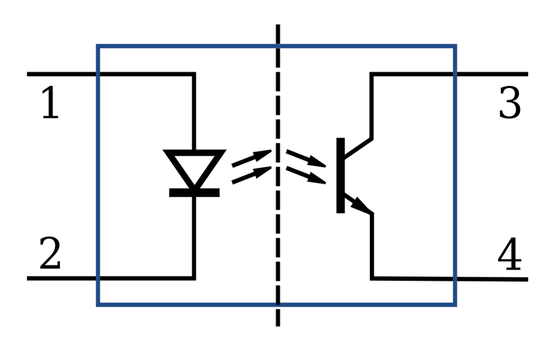
Opto Isolators are also known as Optocouplers. Optocoupler consists of one light-emitting diode and one photosensitive semiconductor which is used to detect the light emitted by led.
2.1) Working:
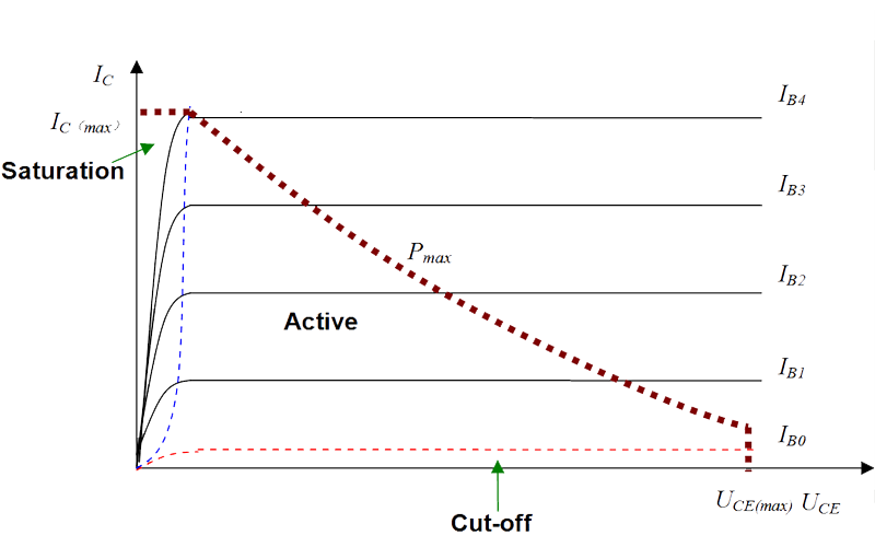
The figure above shows the diagram of the optocoupler. Which consists of an LED and a phototransistor. When the LED is in an off state, the transistor works as an off switch. When the LED is turned on, the light falls on the base terminal of the transistor, causing the Vbe Junction forward bias. When the transistor's (NPN transistor) Vbe junction becomes a forward bias then it acts as a closed switch. Excess of light on the base terminal will flow more electrons from the transistor.
Please have a look at below fig. for more information.
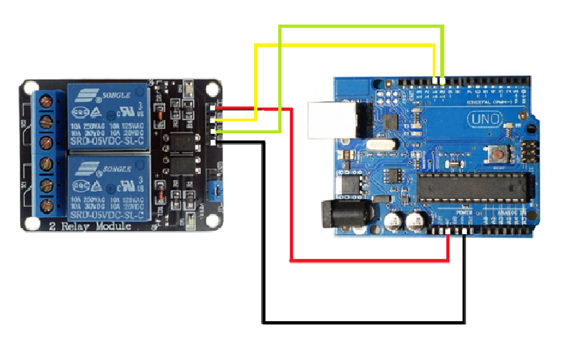
Opto-coupler Relay Circuit with Arduino/STM
Sample Arduino Code
int D1=11; //initialize the pin to which relay is connected
void Setup()
{
pinMode(D1,OUTPUT); //declared as output
}
void loop()
{
digitalWrite(D1,HIGH); //set D1 to high
delay(1000);
digitalWrite(D1,LOW); //set D1 to low
delay(1000)
}


