Speed Control of DC Motor
The speed control mechanism is applicable in many cases like controlling the movement of robotic vehicles. Know how it is achieved below.

The speed control mechanism is applicable in many cases like controlling the movement of robotic vehicles, movement of motors in paper mills and the movement of motors in elevators where different types of DC motors are used. Speed control of DC motor is one of the most useful features of the motor.
What is DC Motor?
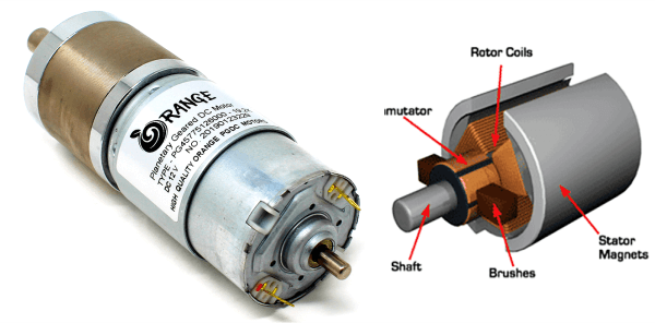
The DC motor is the motor which converts the direct current into the mechanical work. It works on the principle of Lorentz Law, which states that the current carrying conductor placed in a magnetic and electric field experience a force. To learn more about DC motors, visit Working Principle of DC motor and check out the related details.
MUST READ ON DC MOTORS:
- Different Types of DC Motor
- Working Principle of DC Motor
- Difference Between AC and DC Motor
- Applications of Dc motor
Speed Control of DC motor
Often we want to control the speed of a DC motor on demand. This intentional change of drive speed is known as speed control of a DC motor.
We can control the speed of DC motor manually or through an automatic control device. This is different to speed regulation – where the speed can regulate against the natural change in speed due to a change in the load on the shaft.
The speed of a DC motor (N) is equal to
N = K (V – IaRa)/ ø Where, K is a constant.
This implies three things:
- Speed of the motor is directly proportional to supply voltage.
- The Speed of the motor is inversely proportional to armature voltage drop.
- The motor speed is inversely proportional to the flux due to the field findings
Thus, the speed of a DC motor can control in three ways:
- By varying the flux, and by varying the current through field winding
- By varying the armature voltage, and the armature resistance
- Through the supply voltage
1. Flux Control Method
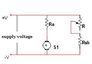
Due to the field winding, the magnetic flux varies in order to vary the speed of the motor. As the magnetic flux depends on the current flowing through the field winding, it changes by varying the current through the field winding. This can achieve using a variable resistor in a series with the field winding resistor.
Initially, when the variable resistor keeps at its minimum position, the rated current flows through the field winding due to a rated supply voltage, and as a result, the speed is kept normal. When the resistance increases gradually, the current through the field winding decreases. This in turn decreases the flux produced. Thus, the speed of the motor increases beyond its normal value.
2. Armature Control Method
The controlling of armature resistance controls the voltage drop across the armature. With this method, the speed of the DC motor can control. This method also uses a variable resistor in series with the armature.
When the variable resistor reaches its minimum value, the armature resistance is at normal one. Therefore, the armature voltage drops. When the resistance value gradually increases, the voltage across the armature decreases. This in turn leads to decrease in the speed of the motor. In this way, this method achieves the speed of the motor below its normal range.
3. Voltage Control Method
Both the above mentioned methods cannot provide speed control in the desirable range. Moreover, the flux control method can affect commutation. Whereas the armature control method involves huge power loss due to its usage of resistor in series with the armature. Therefore, a different method is often desirable – the one that controls the supply voltage to control the motor speed.
In such a method, the field winding receives a fixed voltage, and the armature gets a variable voltage. One such technique of voltage control method involves the use of a switch gear mechanism to provide a variable voltage to the armature. Another one uses an AC motor driven Generator to provide variable voltage to the armature (named as Ward-Leonard System).
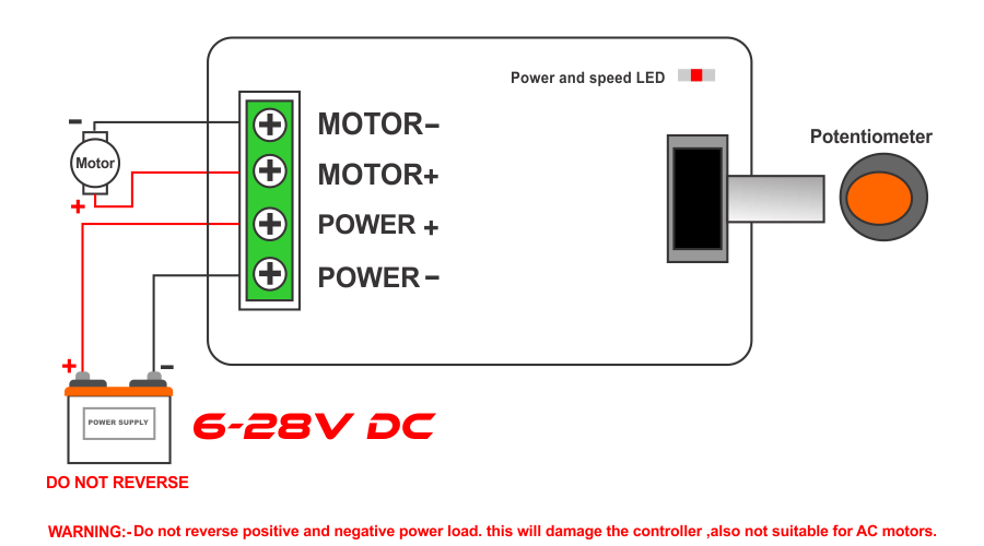
Apart from these two techniques, the most widely used technique is the use of pulse width modulation to achieve speed control of a DC motor. PWM involves application of varying width of pulses to the motor driver to control the voltage applied to the motor. This method proves to be very efficient as the power loss keeps at minimum, and it doesn’t involve the use of any complex equipment.
PWM is achieved by varying the pulses applied to the enable pin of the motor driver IC to control the applied voltage of the motor. The variation of pulses is done by the micro controller, with the input signal from the push buttons.
We hope that we covered all the details and relevant description on DC motor speed control.
We at Robu.in hope that you found it interesting and that you will come back for more of our educational blogs.


each time i used to read smaller content that as well cleɑr their motive, and that is also hapρening wіth this
ρіece of writing which I am reading һere.
I’m extremely thankful to the writer of this post. This was a quick guide to revise old but important concepts. Thank you so much again.
So good