Real-Time YouTube Subscriber Display with Arduino Nano ESP32 and MAX7219 Display Module
The Arduino Nano ESP32 is Arduino’s latest and greatest IoT development board. This small yet powerful board is built around the ESP32-S3 microcontroller and offers a wide range of

The Arduino Nano ESP32 is Arduino's latest and greatest IoT development board. This small yet powerful board is built around the ESP32-S3 microcontroller and offers a wide range of features. This board has Wi-Fi and Bluetooth connectivity, 16 MB of flash memory, 512 KB of SRAM, and a 32-bit dual-core processor. It also supports Arduino and Micro Python programming, compatibility with Arduino IoT Cloud, and has a convenient USB-C connector to upload or debug a program. Overall, it provides all the tools necessary for seamless IoT development.
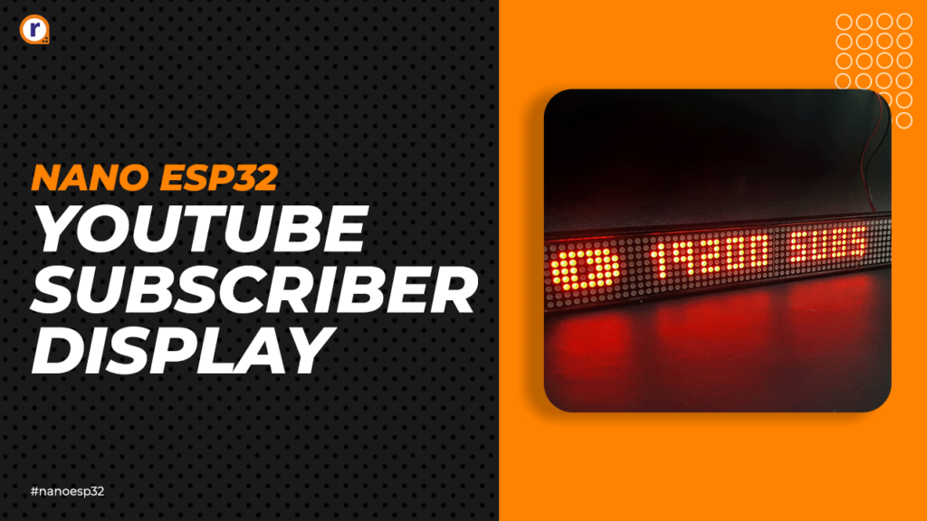
After considering all these features, we have decided to create a YouTube Subscriber Display using the Arduino Nano ESP32 and MAX7219 Display Module, doing so will not only demonstrate the capabilities of the new board but also help you learn about the potential challenges you may encounter while working with it. So, without further ado, let's begin building!
What is an Arduino Nano ESP32 board?
The Arduino Nano ESP32 is a powerful development board, combining Nano's form factor with ESP32-S3 features. It has a dual-core 32-bit LX7 microprocessor, 16 MB flash, 8 MB RAM, and Wi-Fi/Bluetooth 5.0 support. With Arduino and MicroPython compatibility, it's ideal for various IoT projects.
How to program the Arduino Nano ESP32?
The process to upload the code is like other Arduino boards. However, the Arduino Nano ESP32 utilizes the DFU method and JTAG for uploading, so you need to use the ZADIG tool to update the driver before you can upload your program.
How to update the Arduino Nano ESP32 Driver?
You need to use the Zadig USB driver installer to update the driver for the Arduino Nano ESP32 board.
Components Required to Build the YouTube Subscriber Display
The components required to build the YouTube Subscriber Display are very simple and you can find most of it in your local hobby store. The list of components is shown below
- Arduino Nano ESP32 Development Board – 1
- Max7219 Dot Matrix Display – 2
- Jumper Wires – 5
- DC barrel Jack – 1
- 3D Printed Encloser - 1
- Acrylic sheet for cover – 1
- Solder and Soldering Iron
- Power Adapter – 1
The Arduino Nano ESP32 Board
 The Arduino Nano ESP32 is a highly capable development board that combines the compactness of the Nano form factor with the robust features of the ESP32-S3 microcontroller. Its powerful dual-core Xtensa 32-bit LX7 microprocessor, coupled with 16 MB flash memory and 8 MB RAM, provides necessary computational and storage capacity for demanding IoT applications. Wi-Fi and Bluetooth 5.0 compatibility, as well as support for Arduino and MicroPython programming languages, further enhance its versatility. Other features include a USB-C connector, 14 digital I/O pins, 3 analog input pins, and dual 3.3 V and 5 V power supply options. Suitable for a wide range of IoT projects, from smart home devices to industrial automation, the Arduino Nano ESP32 presents a robust, adaptable option for tech enthusiasts and professionals alike.
Setting up the New Arduino Nano ESP32
Setting up the Arduino Nano ESP32 is very simple, and it just works like an Arduino UNO board. But you need to install the DFU drivers to upload the code.
As you can see in the above image when you first connect the Arduino Nano ESP32, the driver will not install automatically. If you open the Device Manager, it will show just like the above image.
To install the driver, you need download the ZADIG driver Installer, once you open the software, it should automatically detect the missing driver, and you just need to click the install button, it will take few munities to install the driver, and once it's done, you can upload the code to your Arduino Nano ESP32.
The MAX7219 Dot Matrix Display
 The MAX7219 is an integrated circuit that serves as a versatile and efficient solution for driving dot matrix displays. Developed by Maxim Integrated, it is widely used in applications requiring multiplexed LED displays, such as digital clocks, scoreboards, and information panels. The MAX7219 can control an 8x8 LED matrix or an array of 7-segment displays, making it ideal for presenting numbers, characters, and even basic graphics. Its ease of use, compact design, and serial interface capabilities have made it a popular choice among hobbyists and professionals alike. By providing a straightforward way to cascade multiple MAX7219 devices, it enables the creation of larger displays with minimal wiring complexity. Its ability to control brightness and the refresh rate of the LEDs ensures clear and vibrant visuals. Overall, the MAX7219 dot matrix display driver offers an efficient, cost-effective, and user-friendly solution for various projects requiring LED matrix control.
Circuit Diagram of the Arduino Nano ESP32 based Subscriber Display.
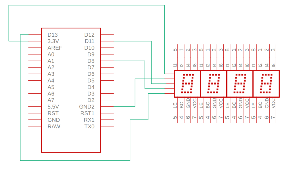
The schematic diagram of the Arduino Nano ESP2 based YouTube Subscriber display is simple and easy to understand, the complete schematic diagram is shown below.
 in the schematic we connect the Pins as shown in the table below.
|
Arduino Nano ESP32 Pin |
MAX7219 Dot Matrix Display Pin |
|
3.3V |
VCC |
|
GND |
GND |
|
CS |
D8 |
|
CLK |
D13 |
|
DATA |
D11 |
Code Explanation: Arduino Nano ESP32 based YouTube Subscriber Counter
The code to build the YouTube subscriber display is simple and easy to understand . so we start our code by including all the required library's. most of the Libraries are used here can be found in the Arduino Library Manger, but you have to Download the theSwedishMaker library from GitHub.
#include <MD_Parola.h>
#include <MD_MAX72xx.h>
#include <SPI.h>
#include "Arduino.h"
#include <WiFi.h>
#include <WiFiClientSecure.h>
#include <HTTPClient.h>
#include <ArduinoJson.h>
#include "theSwedishMaker.h"
Next we have define the Hardwear type, the Max Devices and the CS_Pin. which all is self explanatory.
#define HARDWARE_TYPE MD_MAX72XX::FC16_HW
#define MAX_DEVICES 8
#define CS_PIN 8
Next we have our Wi-Fi credential and API information, for this API we are using a Custom API to get the YouTube Sub data, but you can use the YouTube API directly to get this information.
const char* ssid = "xxx";
const char* password = "xxxxxxxxxxxxxxxxxxx";
const char* serverName = "https://robu.in/";
Next, we have declarerd, all the required variables, we start of with the subsCount variable and next we declair the instance for the MD_Parola library and WiFiClientSecure library.
Next we have the Void Setup() function, in the setup function we initialize the matrix display and set its intencity, next we set the font for the display, setting the font will allow us to print custom characters on the display.
void setup() {
P.begin();
P.setIntensity(10);
P.setFont(fontSubs);
P.displayClear();
Next in the Setup() function we have init the serial and we have connected to the Wi-Fi hotsopt
Serial.begin(115200);
Serial.print("Connecting WiFi ");
WiFi.begin(ssid, password);
P.print(" WiFi...");
while (WiFi.status() != WL_CONNECTED) {
Serial.print(".");
delay(500);
}
Serial.println("");
Serial.print("Connected: ");
Serial.println(WiFi.localIP());
client.setInsecure();
}
Next we have our loop function, in the loop function we have check the Wi-Fi connection, get the data from our custom API, Deserilize the received JSON Data, and print the data on the display with scrolling effect.
void loop(void) {
P.print("fetching");
if ((WiFi.status() == WL_CONNECTED)) {
HTTPClient http;
http.begin(serverName);
int httpResponseCode = http.GET();
if (httpResponseCode > 0) {
String response = http.getString();
const size_t capacity = JSON_OBJECT_SIZE(2) + JSON_OBJECT_SIZE(7) + 370;
DynamicJsonDocument doc(capacity);
deserializeJson(doc, response);
JsonObject data = doc["data"];
const char* subscriberCount = data["subscriberCount"];
subsCount = subscriberCount;
Serial.print("Subscriber Count: ");
Serial.println(subscriberCount);
} else {
Serial.print("Error code: ");
Serial.println(httpResponseCode);
}
http.end();
} else {
Serial.println("Error in WiFi connection");
}
String T = "* " + String(subsCount) + " SUBS";
char charArray[T.length() + 1];
T.toCharArray(charArray, T.length() + 1);
P.displayText(charArray, PA_CENTER, 100, 0, PA_SCROLL_LEFT, PA_SCROLL_LEFT);
while (1) {
// Serial.println(subsCount);
// P.print(T);
if (P.displayAnimate()) {
P.displayReset();
}
}
}
That is all there is for the code and you can find the the full code in final section of this post.
Conclusion
In this project, we successfully created a YouTube Subscriber Display using the Arduino Nano ESP32 and MAX7219 Display modules. We designed a 3D model and utilized laser cutting to create an enclosure for the display. The process involved fetching subscriber count data from a custom API and displaying it on the LED matrix with a scrolling effect. The project showcased the seamless integration of the Arduino Nano ESP32 with the MAX7219 module for effective data display applications. Through this project, we gained valuable insights into Wi-Fi connectivity, API interaction, JSON data handling, and driving LED matrix displays. The Arduino Nano ESP32's versatility and compatibility with various libraries make it an excellent choice for IoT projects, with endless possibilities for creative developments.


