Raspberry Pi Pico vs Arduino which to choose?
In this article, we will compare Raspberry Pi Pico and Arduino Uno, the two best powerful and cheap microcontrollers all around the world.

Are you a Techno geek and stuck with the question in your mind which to choose Raspberry Pi’s latest microcontroller, “Raspberry Pi Pico” or Arduino?
Then go through these posts. I hope that you will get a clear solution on your next microcontroller choice and have no more doubt.
With its latest release this year Raspberry Pi has also entered the world of microcontroller and cleared its vision.
What is Arduino?
If you are a beginner and don’t know about Arduino, here is a short description.
Arduino is an open-source electronics platform based on easy-to-use hardware and software.
Over the years Arduino has been the brain of thousands of projects, from everyday objects to complex scientific instruments.
There are many different types of Arduino microcontroller boards to choose from. Almost all the Arduino boards have ATmega microcontrollers as a control unit.
With Arduino's easy-to-use IDE software for beginners, the Arduino is easier to learn to program as it uses a simplified version of C++ compared to other programming software. Arduino software runs on cross-platforms such as Linux, Windows, Macintosh OS, and other platforms.
What is Raspberry Pi?
Raspberry Pi is a single-board credit card-sized computer that plugs into your TV or display, and a keyboard and mouse.
You can use it to learn to code, build electronics & robotics projects, learn and connect with the IoT world, and in addition many of the things that your desktop PC does, like spreadsheets, word processing, browsing the internet, and playing games. It also plays high-definition video.
The Raspberry Pi is being used by adults and children all over the world to learn programming and digital making.
What is Raspberry Pi Pico?
Raspberry Pi Pico is the first-ever microcontroller board from the Raspberry Pi foundation. It is a low-cost, high-performance microcontroller board with flexible digital interfaces.
Pico is designed on a powerful RP2040 microcontroller chip. The RP2040 features a dual-core ARM Cortex M0+ processor, flexible clock running up to 133 MHz.
It has a simple design so that more people can understand hardware and software easily that helps them to create gadgets and products more frequently. The Pico board features a multi-purpose castled hole/pad design, allowing headers to be soldered onto the pads as commonly seen on development boards, or the entire board can be treated as a surface-mountable module.
Pico also has the power and flexibility to serve professional users, whatever your application from machine learning, smart homes, wearables, to robotics.
Functionality and uses of GPIO
Raspberry Pi Pico
Raspberry Pi Pico has 40 pins as previous boards but they are way more different than the previous one. Out of 40 pins, there are 26 multi-function GPIO pins operating at 3.3V. The remaining pins are Ground and Power pins.
GPIO pins support specialist communication protocols such as I2C, SPI, and UART serial ports also 12-bit ADC and controllable PWM channels.
- 26 × multi-function 3.3V GPIO pins
- 2 × SPI, 2 × I2C, 2 × UART, 3 × 12-bit ADC, 16 × controllable PWM channels
- 8 × Programmable I/O (PIO) state machines for custom peripheral support.
- The castellated module allows soldering directly to carrier boards.
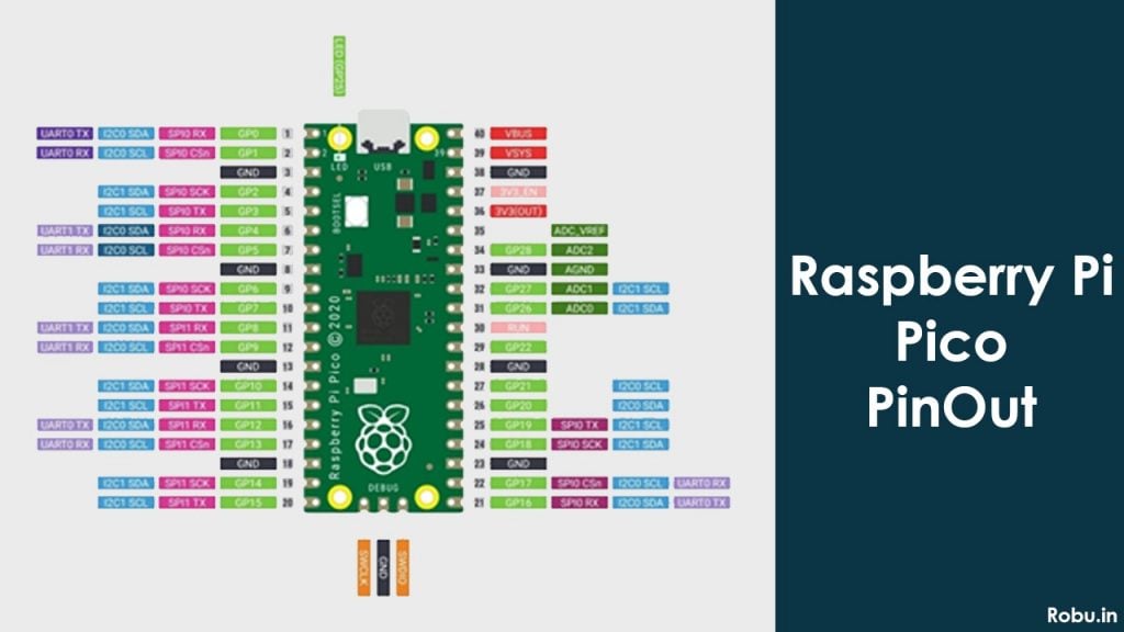
| Pin Category | Pin Name | Details |
| Power | VBUS, VSYS, 3V3(OUT), GND | VBUS: USB input voltage, typically 5V. VSYS: Main system input voltage pin and can be varied in range 1.8V to 5.5V. 3V3 (OUT): main 3.3V supply to RP2040 and its I/O, generated by the onboard SMPS. GND: Ground pins. |
| System Control | 3V3 (EN), Run | 3V3 (EN): Onboard SMPS enable pin, pulled high (to VSYS) via a 100K resistor. Run: RP2040 enable pin, and has an internal (on-chip) pull-up resistor to 3.3V of about ~50K Ohms. |
| Analog Pins | ADC_VREF, AGND | ADC_VREF: ADC power supply (and reference) voltage, generated on Pico by filtering the 3.3V supply. AGND: Ground reference for GPIO26-29, ADC performance is not critical, this pin can be connected to digital ground. |
| Inbuilt LED | GP25 | To turn on the inbuilt LED. |
| Programming | BOOTSEL | To mount the Pico board as a mass storage volume. |
| General Purpose IO | GPIO 0 – GPIO 22, GPIO 26 - 28 | GPIO0 to GPIO22 are digital-only. GPIO 26-28: Can be used either as digital GPIO or as ADC inputs |
Arduino Uno
Arduino Uno has 14 digital I/O pins, 6 analog input pins, Power pins, Ground pins, IOREF pins, AREF pin.
Out of 14 digital pins, 6 are PWM pins.
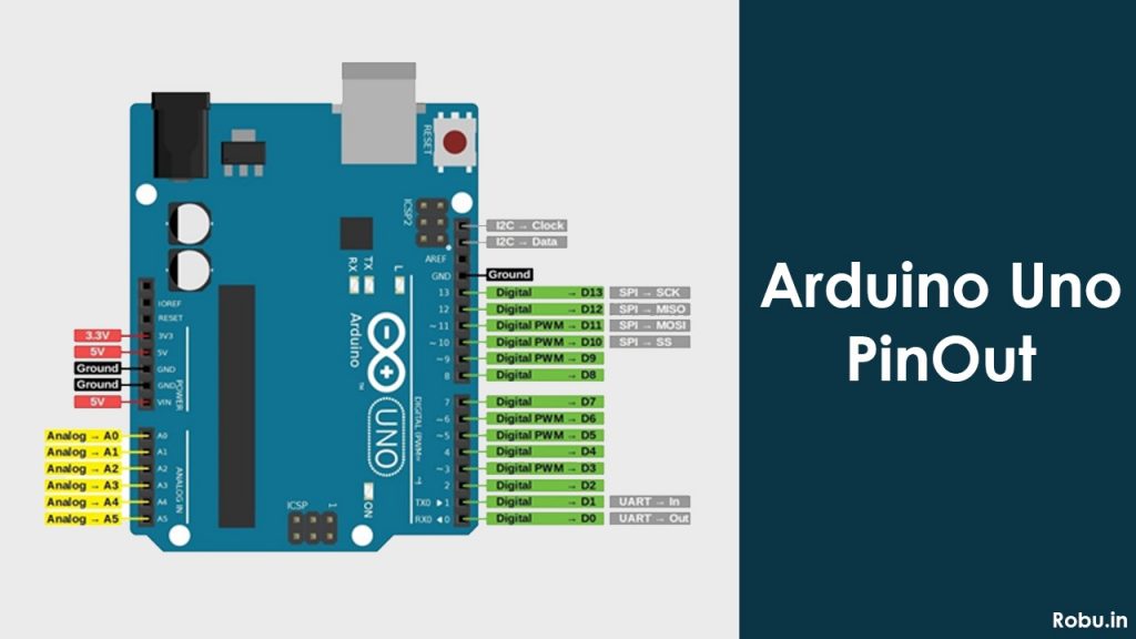
| Pin Category | Pin Name | Details |
| Power | Vin, 5V, 3.3V, GND | Vin: Input voltage to Arduino when using an external power source. 5V: Regulated power supply used to power microcontroller and other components on the board. 3.3V: 3.3V supply generated by the onboard voltage regulator. The maximum current drawn is 50mA. GND: ground pins. |
| Reset | Reset | Resets the microcontroller. |
| Analog Pins | A0 – A5 | Used to provide analog input in the range of 0-5V |
| Input/Output Pins | Digital Pins 0 - 13 | Can be used as input or output pins. |
| Serial | 0(Rx), 1(Tx) | Used to receive and transmit TTL serial data. |
| External Interrupts | 2, 3 | To trigger an interrupt. |
| PWM | 3, 5, 6, 9, 11 | Provides 8-bit PWM output. |
| SPI | 10 (SS), 11 (MOSI), 12 (MISO) and 13 (SCK) | Used for SPI communication. |
| Inbuilt LED | 13 | To turn on the inbuilt LED. |
| TWI | A4 (SDA), A5 (SCL) | Used for TWI communication. |
| AREF | AREF | To provide a reference voltage for input voltage. |
These 14 digital I/O pins are used as input or output pins by having different modes and functions such as pinMode(), digitalRead(), and digitalWrite() in Arduino programming.
Each pin operates at 5V and can provide or receive a maximum of 40mA current, and has an internal pull-up resistor of 20-50 kOhms which are disconnected by default.
Out of these 14 pins, some pins have specific functions as listed below:
- Serial Pins 0 (Rx) and 1 (Tx): Rx and Tx pins are used to receive and transmit TTL serial data. They are connected with the corresponding ATmega328P USB to TTL serial chip.
- External Interrupt Pins 2 and 3: These pins can be configured to trigger an interrupt on a low value, a rising or falling edge, or a change in value.
- PWM Pins 3, 5, 6, 9, and 11: These pins provide an 8-bit PWM output by using the analogWrite() function.
- SPI Pins 10, 11, 12, 13: These pins are used for SPI (Serial peripheral interface) communication. SPI is a synchronous serial communication i.e. the clock is a must for communication purposes.
- Pin 10 is SS i.e. Slave Select. Master can use this pin to enable and disable specific devices
- Pin 11 is MOSI i.e. Master Out Slave In. This is the Master line for sending data to peripherals.
- Pin 12 is MISO i.e. Master In Slave Out. This is the Slave line for sending data to Master.
- Pin 13 is SCK i.e. Serial Clock. The clock pulses synchronize data transmission generated by Master.
- In-built LED Pin 13: This pin is connected with a built-in LED, when pin 13 is HIGH – the LED is on and when pin13 is LOW, it’s off.
Along with 14 Digital pins, there are 6 analog input pins, each of which provides 10 bits of resolution, i.e. 1024 different values. They measure from 0 to 5 volts but this limit can be increased by using the AREF pin with the analogReference() function.
- AREF: Used to provide reference voltage for analog inputs with analogReference() function.
- Reset Pin: Making this pin LOW, resets the microcontroller.
Analog pin 4 (SDA) and pin 5 (SCL) also used for TWI (Two-wire interface) communication using the Wire library.
With a Castellated module and 40 GPIO pins which include I2C, SPI, UART communication protocols, and PIO, three analog input pins the Pico offers a large variety of connecting and interfacing options.
While Arduino Uno lacks some of these features thus making Raspberry Pi Pico a great choice to go with.
Microcontroller
RP2040 microcontroller
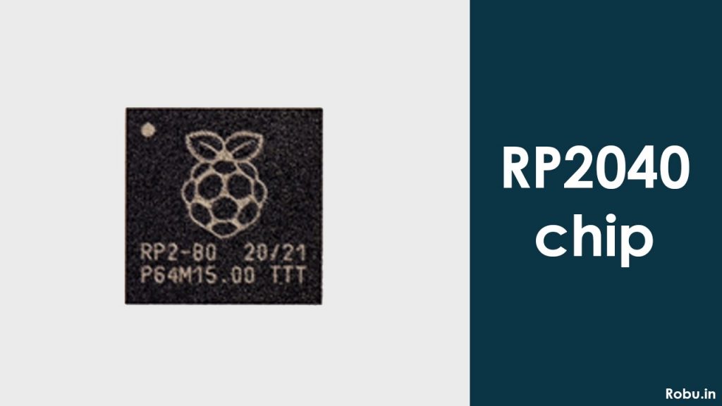
Raspberry Pi Pico, comes with the latest RP2040 microcontroller on it. RP2040 is a microcontroller from the Raspberry Pi foundation.
RP2040 is a Dual-core Arm Cortex-M0+ processor with flexible clock speed running up to 133 MHz, 264kB of SRAM, 2MB of on-board, and up to 16 MB off-chip flash memory.
ATmega328P microcontroller
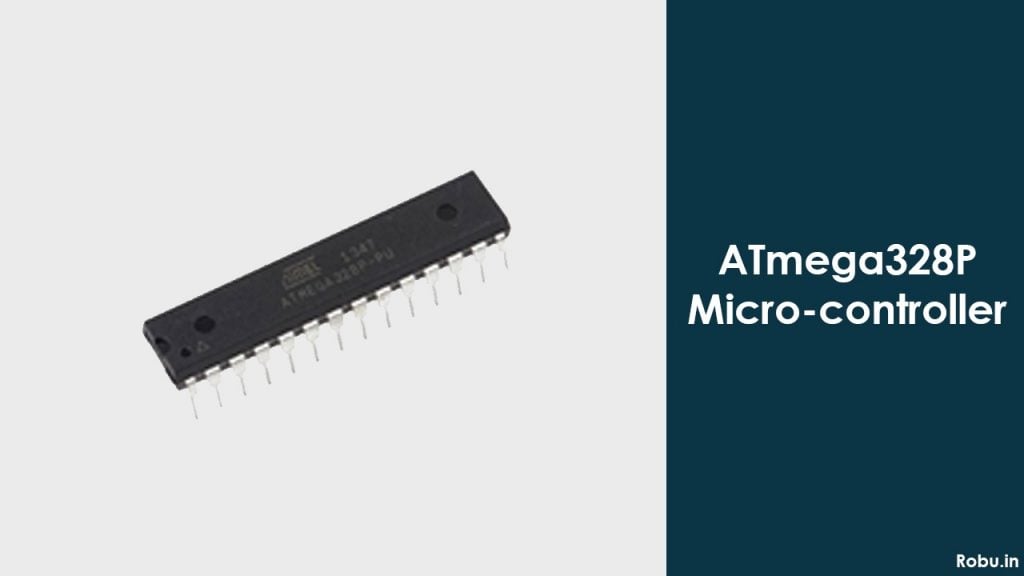
Whereas on the other hand, Arduino Uno comes with ATmega328P an 8-bit AVR family microcontroller, with a clock speed of 16 MHz, 2kB of SRAM, and 32kB of flash memory.
Dual-core processors behave like two single-core processors running on a single chip. Dual-core processors are able to divide information for processing by multiple units. Each processor core has its own cache and an interface that connects to the system bus. This type of processor executes two complete instructions at the same time. This enables the processors to share the workload between the two cores and enhance processing capacity.
ATmega328P is a low-power CMOS 8-bit microcontroller based on the AVR enhanced RISC architecture. By executing powerful instructions in a single clock cycle, the ATmega328P achieves throughputs approaching 1MIPS per MHz allowing the system designed to optimize power consumption versus processing speed.
Clock speed is the rate at which a microcontroller CPU executes instructions. The Higher the clock speed, the more instructions the CPU can execute per second.
With a 133 MHz clock rate, we can say that RP2040 executes all instructions at a very high speed than ATmeg328P.
SRAM is a type of Random access memory used to store each binary logic '1' and '0' bit. It is a volatile type of memory and the data is lost when no power is provided. SRAM is generally used for high-speed registers, caches, and relatively small memory banks.
With 264 kB of SRAM memory RP2040 again wins the race and is the best option to go rather than ATmega328P with just 2 kB of SRAM memory.
Flash memory is a non-volatile memory chip used for storage and for transferring data. Its non-volatile meaning it can hold data even without the presence of power. Thus higher the flash memory, the more will be data stored.
Here you need to know that RP2040 is such a powerful microcontroller that even Arduino has officially announced to use it in their upcoming Arduino Nano RP2040 connect board. Arduino and Raspberry Pi have collaborated and planning something great ahead in the field of microcontrollers.
Programming
Raspberry Pi Pico
Raspberry Pi Pico comes with two different platforms for programming and also two different programming languages support i.e. “C/C++ or MicroPython”.
For programming Pico, we can use Serial Wire Debug Port or the Special USB Mass Storage Device Mode.
I would recommend you to program it through the Special USB Mode, in this mode you just need to press and hold the BOOTSEL button on the board, it will pop up as USB mass storage on the screen now drag the special UF2 file and drop it onto the USB mass storage device option on the screen the disc will write the file to flash and restart the Pico board.
If you are a beginner then MicroPython is best suited for you and if you are an advanced user you can go for any of the suitable languages.
Pico provides two choices for programming software in both languages.
For programming MicroPython you can use either ThonnyIDE with version 3.3.0 and above or any comfortable Python Shell. I would suggest you use Python ThonnyIDE.
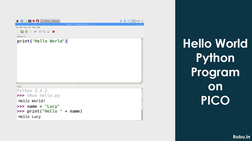
Again, for programming in C/C++ languages, there are two options available.
Either you write your code in any text editor of your choice build the file and flash it with Pico or go for Microsoft’s Visual Studio Code. In the second option i.e. in Visual Studio code just build your own graphical workflow and flash the program.
If you want to reprogram your Pico board then simply drag and drop a UF2 file in a mass storage device option as discussed earlier or use SWD port it can reset and load the code without any button press.
Arduino Uno
Arduino Uno and all other Arduino boards can be programmed through Arduino IDE it is an open-source software from Arduino.cc.
Also, there are another two softwares in which Arduino boards can be programmed PlatformIO and Arduino Create (Cloud version of Arduino IDE for IoT-based projects). All Arduino softwares are compatible with Windows, Linux, or MAC OS systems.
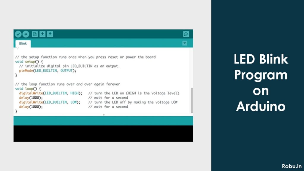
Arduino supports C and C++ programming language with some special rules of code structuring. Arduino IDE has a large number of inbuilt libraries and examples, also it has the option to select the board of our own choice.
To program Arduino Uno you need one USB to a type-B connector cable. Connect type-B port to Arduino and USB port to PC/Laptop, after connecting to PC/Laptop you need to select the board in Arduino IDE, and then you can program your Arduino Uno.
Finally, we can say that Pico comes with two language support options to program, MicroPython, and C/C++ in two different software shells for both languages.
While Arduino provides just one language option of C/C++ in three different Arduino supported software. Thus making Pico a better option to go through for all users.
Powering Boards
Raspberry Pi Pico
Raspberry Pi Pico supports 1.8 – 5.5V DC input power. Raspberry Pi Pico comes with two options to power the board. First is power through a USB port or using VBUS and VSYS.
VBUS this pin is a micro-USB input voltage pin, connected to micro-USB port pin 1. Normally it is 5V and if USB is not connected then 0V. VSYS this pin is the main system input voltage pin and can be varied in the range of 1.8V to 5.5V.
In my opinion, if you are a beginner and don’t have your hands-free Microcontroller then you should go for the first option i.e. powering through the USB port.
But in this case, you need to learn power through the second option i.e. VBUS and VSYS as it is the most required to make your board portable through projects.
To power, through VBUS and VSYS we have many options such as Li-ion Cells, 3 AA cells in series, or any other fixed power supply in the range of 2.3V – 5.5V.
Arduino Uno
The operating voltage of Arduino Uno is 5V and the recommended input voltage is 7-12V (Note: Input Voltage limit of Arduino board is 6 – 20V but supplying more than 12V is not recommended it can harm your board).
For powering Arduino Uno there are three different types of options available:
- Power using the USB port
- Power using DC barrel power jack
- Power using external power supply
Powering through a USB port is a very easy task, simply get the Arduino Uno cable. The cable has two ends Type-B and USB. Now connect the type-B port to the Arduino and USB port to your PC/Laptop. The same used to program the Arduino Uno as we have discussed above in our programming section.
For powering through DC barrel jack get one AC – DC power adapter with an output voltage ranging from 7-12V and simply plug in the Arduino Uno board. It is as easy as plug-in and play.
Another powering option for Arduino Uno includes external power supplies such as 9V batteries. There are another two options available here:
Use the Vin pin on the board, simply plug the positive terminal of your 9V battery into the Vin pin and the negative terminal of the battery with the ground.
Or you can use a 5V pin available on the board, to use this option you need one voltage regulator as this is a fixed 5V pin, and supplying more than 5.5V can damage the board.
Also, some tests have revealed that Pico draws more current than Arduino Uno when supplied with the same amount of power supply for running some NeoPixel LEDs.
Thus we can say that this makes Arduino Uno a more efficient board in terms of power consumption and power supply options.
Ease of Use
Raspberry Pi Pico is a very compact microcontroller board with dimensions 21 x 51 mm i.e. smaller than a credit card, this allows the board to fit easily anywhere consuming a very small area and the user to easily fit any project by soldering castellated points on the board with any sensor.
On-board Pico has one BOOTSEL button to program the board and one USB port to power, configure or program the board. This makes the board very handy and portable.
But when it comes to Arduino Uno it is quite bigger in size and occupies more space than Pico. Arduino Uno comes with pre-installed header pins having dimensions 70 x 54 x 12 mm i.e. near about the size of a palm.
On-board Arduino Uno has one type-B port, DC barrel power jack, 32 female header pins, and in DIP package board DIP mounted ATmega328P processor (in SMD mount Arduino Uno processor is mounted in SMD style), ICSP pins, Reset button.
When used in projects it will occupy more area than Pico thus expanding the space of the microcontroller in the project.
Conclusion
As now we have seen the complete description and specs of both the boards, we can say that when it comes to the perspective of the cost we get Official Raspberry Pi Pico board just at INR. 350/- whereas if we want the original Arduino Uno board it costs approx. INR 1500/- although there are many clone Arduino Uno boards within INR 500/- that work the same as well with no difference.
Practically, if you are a beginner in the world of microcontroller, Arduino Uno is the best suitable board to learn. There are no. of pre-installed libraries, examples available in Arduino IDE and the Arduino community to help you out. In the past 15 years, Arduino is the biggest community, since Raspberry Pi Pico is the latest there is not a bigger family to help you out but it gives you a golden chance to grab the opportunity of becoming one of the experts.
On Arduino Uno you can learn, create several projects based on IoT, Artificial Intelligence (AI), Machine Learning (ML), Security systems, motion detectors, Industrial and home automation, etc. with the help of very low-cost sensors readily available in the market and several links to help you out with, in case of Raspberry Pi Pico it is said to perform the same level of projects but there are not as many links readily available to help you.



Nice article, thank you. I’m new to Pico, just waiting to check how it runs.
Just few mentions related to the programming environments for Arduino, from my experience:
– also, Microchip Studio is available for Arduino coding (near the already-mentioned IDEs) – still C/C++ as programming language, but rather interesting IDE (focused on already experienced Arduino users, though);
– perhaps importantly – in terms of supported programming languages, MATLAB has an interesting support for Arduino (in either Matlab or Simulink languages); it might not include as many examples as Arduino IDE or other IDEs, but I think it might also be an interesting way to work with Arduino, as an alternative to the C/C++ languages. One needs to install the Matlab/Simulink support for Arduino, once Matlab installed. Of course, the drawback is the cost of MATLAB software itself, but, if available, it comes with other way(s) of programming the Arduino board. It seems a rather straight-forward programming procedure, at least for simple projects.