-25%
,

DRV8825 Stepper Motor Driver with Aluminum Heat Sink- Good Quality

(10 customer reviews)
Availability:

Out of stock

Approx Restocking Date: 25 to 30 Days
SKU: 52599
  1. Supply Voltage: 8.2 – 42 VDC.
  2. Current Capacity : 2.2A max(24V).
  3. Continuous current per phase: 1.5 A.
  4. Minimum Logic voltage: 2.5V.
  5. Maximum Logic Voltage: 5V.
  6. Microstep resolutions: full, 1/2, 1/4, 1/8, 1/16, and 1/32.
  7. Dimensions : 15 x 20 mm.
  8. Weight: 4 gm.

 85.00  114.00 (Incl. GST)

  You save(25.4%): ₹ 29.00

Out of stock


Free Delivery above ₹499
Free Delivery
above ₹499
1 Year Warranty
15 Days Warranty
Cash On delivery
Cash on Delivery*

Didn’t find what you are looking for?

You must register to use the waitlist feature. Please login or create an account
Category: Stepper Motor Drivers, Best Prices
Tags: Motor Driver, Steeper Motor, DRV8825

The DRV8825 Stepper Motor Driver with Aluminum Heat Sink is a breakout board for TI’s DRV8825 microstepping bipolar stepper motor driver.

The module has a pinout and interface that are nearly identical to those of the A4988 stepper motor driver carriers, so it can be used as a higher-performance drop-in replacement for those boards in many applications.

The DRV8825 features adjustable current limiting, overcurrent, and overtemperature protection, and six microstep resolutions (down to 1/32-step). It operates from 8.2 – 45 V and can deliver up to approximately 1.5 A per phase without a heat sink or forced air flow (rated for up to 2.2 A per coil with sufficient additional cooling).
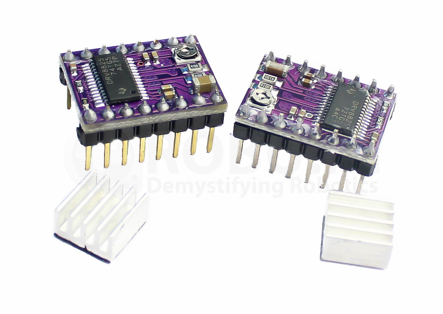
Img 0849

Note: We are supplying two DRV8825 Drivers as DRV8825 Stepper Motor Driver with Aluminum Heat Sink- Good Quality and DRV8825 Stepper Motor Driver with Aluminum Heat Sink- Normal Quality. The difference between them is, the good quality DRV8825 has more number of PCB layers and it features the connecting pins which are of gold plated as compared to other. (refer to above image)


Using the Driver

Wiring Diagram For Drv8825 Stepper Motor Driver


Features :

  1. Microstep resolutions: full, 1/2, 1/4, 1/8, 1/16, and 1/32.
  2. Simple step and direction control interface
  3. Six different step resolutions: full-step, half-step, 1/4-step, 1/8-step, 1/16-step, and 1/32-step
  4. Adjustable current control lets you set the maximum current output with a potentiometer. Hence lets you use voltages above your stepper motor’s rated voltage to achieve higher step rates
  5. Intelligent chopping control that automatically selects the correct current decay mode (fast decay or slow decay)
  6. 45 V maximum supply voltage
  7. Built-in regulator (no external logic voltage supply needed)
  8. Can interface directly with 3.3 V and 5 V systems
  9. Over-temperature thermal shutdown, over-current shutdown, and under-voltage lockout
  10. Short-to-ground and shorted-load protection
  11. 4-layer, 2 oz copper PCB for improved heat dissipation
  12. Exposed solderable ground pad below the driver IC on the bottom of the PCB

Package Includes :

1 x DRV8825 Stepper Motor Driver with Aluminum Heat Sink- Good Quality.

Model Series:

DRV Series, Heat Sink

Voltage Rating (V):

8.2 to 42VDC

Current Rating (A):

1.5 to 2.2

Input Voltage (VDC)

8.2 ~ 42

Logic Voltage (V)

2.5 ~ 5

Max. Current (A)

2.2

Continuous Current (A):

1.5 (per phase)

Length (mm):

15

Width (mm):

20

Weight (g):

4

Shipping Weight 0.005 kg
Shipping Dimensions 4 × 4 × 4 cm
15 Days Warranty

This item is covered with a standard warranty of 15 days from the time of delivery against manufacturing defects only. This warranty is given for the benefit of Robu customers from any kind of manufacturing defects. Replacement will be done against manufacturing defects.


What voids warranty:

If the product is subject to misuse, tampering, static discharge, accident, water or fire damage, use of chemicals & soldered or altered in any way.

Based on 10 reviews

4.1 overall
6
1
2
0
1

Add a review

  1. NaveenR (verified owner)

    These drivers though affordable are extremely fragile. The trimpot on mine broke during the current adjustment! so it became useless now. I would suggest Ya’ll go for branded drivers.

    NaveenR

  2. Chaitanya (verified owner)

    working fine without any issues.

    Chaitanya

  3. owais mech (verified owner)

    it is good at this price but you alo must have to be lucky i brought 2 but 1 is not working but thanks to support team they are very good people.

    owais mech

  4. souvikdey.official (verified owner)

    Amazing product works like a charm and delivery was very fast and efficient

    souvikdey.official

  5. nharishankar (verified owner)

    I’ve been using this for stepper motor for more than a month and my Robot vehicle is working amazing. Don’t buy this anywhere else, I’ve had enough trouble buying it on other places.

    nharishankar

  6. gurpreet80singh

    not useful, burnt within a second.

    gurpreet80singh

  7. ANKIT SHARMA (verified owner)

    This is a fantastic piece of brilliant engineering,very vertalile up to 24 volts ,no any issue of failure like l293d with 24 volts.

    ANKIT SHARMA

  8. mayurkumarchauhan19@gmail.com

    Good , awesome working

    mayurkumarchauhan19@gmail.com

  9. Ravindra V (verified owner)

    This is an excellent stepper driver for 3d printer, CNC machine. I got the delivery in a days time.
    As usual Robu excels in delivery and quality,

    Ravindra V

  10. Amul Agrawal

    ?Good product and good delivery in time

    Amul Agrawal

DRV8825 Datasheet

Connections

Power Dissipation Considerations

I want to control a 3.9 V, 600 mA bipolar stepper motor, but your DRV8825 stepper motor driver carrier has a minimum operating voltage of 8.2 V. Can I use this driver without damaging the stepper motor?
Yes. To avoid damaging your stepper motor, you want to avoid exceeding the rated current, which is 600 mA in this instance. The DRV8825 stepper motor drivers let you limit the maximum current, so as long as you set the limit below the rated current, you will be within specification for your motor, even if the voltage exceed the rated voltage. The voltage rating is just the voltage at which each coil draws the rated current, so the coils of your stepper motor will draw 600 mA at 3.9 V. By using a higher voltage along with active current limiting, the current is able to ramp up faster, which lets you achieve higher step rates than you could using the rated voltage.
My DRV8825 stepper motor driver is overheating but my power supply shows it’s drawing significantly less than 1.5 A per coil. What gives?

Measuring the current draw at the power supply does not necessarily provide an accurate measure of the coil current. Since the input voltage to the driver can be significantly higher than the coil voltage, the measured current on the power supply can be quite a bit lower than the coil current (the driver and coil basically act like a switching step-down power supply). Also, if the supply voltage is very high compare to what the motor need to achieve the set current, the duty cycle will be very low, which also leads to significant differences between average and RMS current. RMS current is what is relevant for power dissipation in the chip but many power supplies won’t show that. You should base your assessment of the coil current on the set current limit or by measuring the actual coil currents.

Please note that while the DRV8825 driver IC is rated for up to 2.5 A per coil, the 0.5 W current sense resistors are only rated for 2.2 A, and the chip by itself will overheat at lower currents. We have found that it generally requires a heat sink to deliver more than approximately 1.5 A per coil, but this number depends on factors such as ambient temperature and air flow. For example, sealing three DRV8825 driver carriers in close proximity in a small box will cause them to overheat at lower currents than a unit by itself in open air.

How do I connect my stepper motor to the DRV8825 stepper motor driver carrier?

The answer to this question depends on the type of stepper motor you have. When working with stepper motors, you will typically encounter two types  unipolar stepper motor and bipolar stepper motor. Unipolar motor have two winding’s per phase, allowing the magnetic field to be reverse without having to reverse the direction of current in a coil, which makes uni-polar motor easier to control than bipolar stepper motors.

The drawback is that only half of the phase is carrying current at any given time, which decreases the torque you can get out of the stepper motor. However, if you have the appropriate control circuitry, you can increase the stepper motor torque by using the unipolar stepper motor as a bipolar stepper motor (note: this is only possible with 6- or 8-lead unipolar stepper motors, not with 5-lead unipolar stepper motors). Unipolar stepper motors typically have five, six, or eight leads.

Bipolar steppers have a single coil per phase and require more complicated control circuitry (typically an H-bridge for each phase). The DRV8824/DRV8825 has the circuitry necessary to control a bipolar stepper motor. Bipolar stepper motors typically have four leads, two for each coil.

The above diagram shows a standard bipolar stepper motor. To control this with the DRV8825, connect stepper lead A to board output A1, stepper lead C to board output A2, stepper lead B to board output B1, and stepper lead D to board output B2. See the DRV8825 datasheet for more information.

If you have a six-lead unipolar stepper motor as shown in the diagram below:

you can connect it to the DRV8825 as a bipolar stepper motor by making the bipolar connections described in the section above and leaving stepper leads A’ and B’ disconnected. These leads are center taps to the two coils and are not use for bipolar operation.

If you have an eight-lead unipolar stepper motor as shown in the diagram below:

You have several connection options. An eight-lead unipolar stepper motor has two coils per phase, and it gives you access to all of the coil leads (in a six-lead unipolar motor, lead A’ is internally connect to C’ and lead B’ is internally connect to D’). When operating this as a bipolar stepper, you have the option of using the two coils for each phase in parallel or in series.

When using them in parallel, you decrease coil inductance, which can lead to increased performance if you have the ability to deliver more current. However, since the DRV8824/DRV8825 actively limits the output current per phase, you will only get half the phase current flowing through each of the two parallel coils. When using them in series, it’s like having a single coil per phase (like in four-lead bipolar steppers or six-lead unipolar steppers use as bipolar steppers). We recommend you use a series connection.

To connect the phase coils in parallel, connect stepper leads A and C’ to board output A1, stepper leads A’ and C to board output A2, stepper leads B and D’ to board output B1, and stepper leads B’and D to board output B2.

To connect the phase coils in series, connect stepper lead A’ to C’ and stepper lead B’ to D’. Stepper leads ACB, and D should be connect to the stepper motor driver as normal for a bipolar stepper motor (see the bipolar stepper connections above).

Questions and answers of the customers

There are no questions yet. Be the first to ask a question about this product.

Only registered users are eligible to enter questions
Country Of Origin: China

You may also like…