Orange Raspberry Pi Advanced Kit
Hello there, and welcome back. In this blog, we will discuss the Orange Raspberry Pi Advanced Kit. This kit is only available on Robu.in.

If you want to learn about the Raspberry Pi and are interested in the Python programming language, then this orange Raspberry Pi Kits is for you.
You will not only learn advanced Raspberry Pi components with this kit, but you will also gain a solid understanding of the Python programming language.
This kit includes a variety of components that will help you learn Raspberry Pi programming more effectively.
There are a few other similar kits on our website; however, if you are completely new to the Raspberry Pi section, we recommend that you start your Raspberry Pi learning journey with the kits listed below.
So that was an introduction to the orange Raspberry Pi Advance Kit; in the following section of this blog, we will learn about interfacing the orange Raspberry Pi kit's components with the Raspberry Pi.
Ultrasonic Sensor With The Raspberry Pi
As you may know, ultrasonic sensors are used to measure distance. Ultrasonic sensors are widely used in obstacle detection robots and do-it-yourself radar projects.
Similar sensors, such as infrared sensors, LIDAR sensors, and sonar sensors, are available on the market and can be used for similar purposes, but we will not go into detail about them in this article. I'll discuss them in future articles.
So that was the basic overview of the ultrasonic sensor. In the following section, we will learn how to connect the ultrasonic sensor to the Raspberry Pi.
How Does The Ultrasonic Sensor Work?
As we all are a member of the DIY community, I'm sure you're familiar with how an ultrasonic sensor works. If you already know about it, you can skip ahead to the coding section of this blog. However, if you are new to this, you can continue with this section.

The Ultrasonic sensor work is similar to Radar sensor work. The transmitter in radar generates radio waves (sound waves), an electromagnetic wave that travels through the air and returns when it encounters an object in its path. The distance is then calculated using a basic high school formula, which is provided below.
Distance = Time x Speed
Time = The amount of time it takes for the sound wave to reach the receiver.
Speed = The sound wave's speed.
Notable Things –
The speed of sound changes as the temperature and humidity change.
The speed of sound, on the other hand, is 4.3 times faster in water than in air.
How To Interface The Raspberry Pi Module With The Raspberry Pi?
Ultrasonic sensors, as previously discussed, have a transmitter (Trigger) that can transmit infrared sound waves and a receiver that receives reflected sound waves (ECHO pin).
It also has power pins, VCC and GND. The image below depicts the ultrasonic sensor's pinout and its interfacing with the Raspberry Pi.
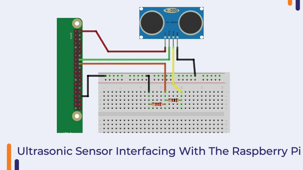
In the next part next part, we will talk about the programming the ultrasonic sensor.
How To Program The Ultrasonic Sensor?
I tried to broaden every line of code in this section, but if I missed something, please let me know.
The first line of code begins by importing modules that can be used to work with the Raspberry Pi's GPIO pins.
import RPi.GPIO as GPIO
import time
RPi.GPIO – This is a Python module designed specifically for the Raspberry Pi. This module facilitates communication with the Raspberry PI's GPIO pins.
Time - We're using the Time Module to add a delay between transmitting and receiving infrared sound waves.
GPIO.setmode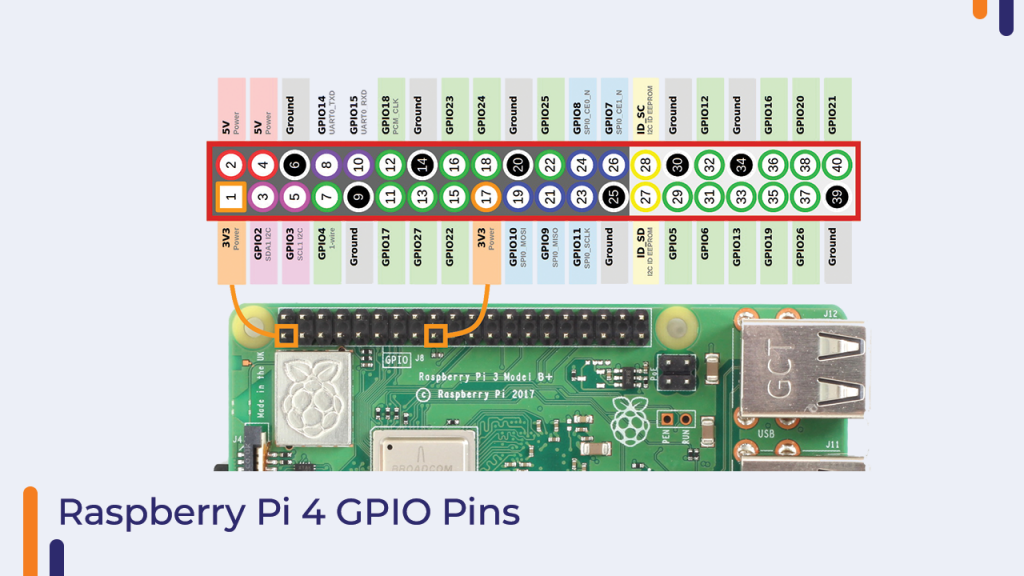
The GPIO SetMode is used to define the numbering scheme that is used to work on the Raspberry Pi GPIO, and there are two ways to do so: GPIO.board and GPIO.BCM.
GPIo.Board - Use the GPIO.setmode (GPIO.board) method to refer to the pin with the number indicated in the circle.
BCM stands for Broadcom chip-specific number and is used in GPIO.setmode(GPIO.BCM).
You can use GPIO.SetMode to refer to a pin number that represents a rectangle (GPIO.BCM).
GPIO ECHO = Raspberry Pi pin number
GPIO TRIG = Raspberry Pi pin number
These lines of code are used to set up the PINs, which will be used to connect the ultrasonic sensor.
If you've ever worked with an Arduino board, you're probably familiar with the pinMode function; this line of code accomplishes the same thing.
We can use this line of code to set the Raspberry Pi's pins as INPUTS or OUTPUTS.
Distance Calculation - Python Code
As mentioned in the datasheet of this ultrasonic sensor we are using the above line of code to make the GPIO pin low for 2 milliseconds.
Time.sleep(2) - This line of code introduces the delay in the process.
GPIO.output(GPIO_TRIG, GPIO.HIGH)
time.sleep(0.00001)
GPIO.output(GPIO_TRIG, GPIO.LOW)
As per the datasheet of the sensor we are introducing the delay in between making GPIO_TRIG pin high and low.
while GPIO.input(GPIO_ECHO)==0:
           start_time = time.time()
while GPIO.input(GPIO_ECHO)==1:
              Bounce_back_time = time.time()
pulse_duration = Bounce_back_time - start_time
distance = round(pulse_duration * 17150, 2)
print (f"Distance: {distance} cm")
Note – If you are not using Python 3.0 or higher version then the above print function will not work. in that case, you can modify the print line with the following line.
print ("Distance:",distance,"cm")In the above line of code, we are calculating the time taken by the pulse to return to the receiver after hitting an object, and for this purpose, we have initialized the pulse duration variable. This variable stores the duration that is taken by the sound wave to return.
If you add all the above lines of code you will get the following code.
import RPi.GPIO as GPIO
import time
GPIO.setmode(GPIO.BCM)
GPIO_TRIG = 11
GPIO_ECHO = 18
GPIO.setup(GPIO_TRIG, GPIO.OUT)
GPIO.setup(GPIO_ECHO, GPIO.IN)
GPIO.output(GPIO_TRIG, GPIO.LOW)
Time.sleep(2)
GPIO.output(GPIO_TRIG, GPIO.HIGH)
Time.sleep(0.00001)
GPIO.output(GPIO_TRIG, GPIO.LOW)
while GPIO.input(GPIO_ECHO)==0:
           start_time = time.time()
while GPIO.input(GPIO_ECHO)==1:
              Bounce_back_time = time.time()
pulse_duration = Bounce_back_time - start_time
distance = round(pulse_duration * 17150, 2)
print (f"Distance: {distance} cm")
GPIO.cleanup()
Conclusion – How To Interface The Ultrasonic Sensor With The Raspberry Pi?
In this section, we learned how to interface the ultrasonic sensor with the Raspberry Pi. If you have any doubts then please let us know. In the next section, we will learn to interface the Capacitive Touch Sensor with the Raspberry Pi.
Capacitive Touch Switch And Buzzer With The Raspberry Pi
We'll learn how to use the touch switch and how to activate the buzzer when it's touched in this section.
When it comes to the capacitive touch switch, as the name suggests, this sensor is a switch that turns on when we touch it.
But how does it know when it is being touched?
A human body is charged in some way. A small amount of electrical charge passes through our body when we touch the capacitive switch's surface, changing the capacitance of the switch.
By detecting a change in the capacitance of the capacitive switch, it is possible to determine whether or not the switch is touched.
So, that was a basic introduction to the capacitive touch switch; if you have any questions, please contact us. The capacitive switch and buzzer module will be interfaced with the Raspberry Pi 4 in the next section of the section.
How To Interface The Capacitive Touch Switch And Buzzer Module With The Raspberry Pi?
It is very simple to connect the capacitive touch and buzzer modules to the raspberry pi.
We can connect the capacitive touch and buzzer modules directly to the Raspberry Pi's GPIO pins.
The interfacing diagram of the capacitive touch switch and buzzer module with the Raspberry Pi is shown in the image below.
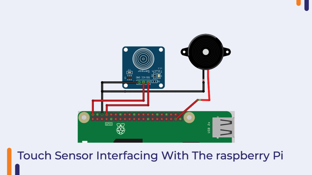
How To Program The Capacitive Touch Switch?
In this section, we will go over the code that we will use to communicate with the capacitive touch switch.
In this case, the capacitive touch switch serves as the input module, and the buzzer is activated based on the received input.
As a result, the capacitive switch must be classified as an input device and the buzzer as an output device.
After we've completed the initial setup, we'll need to use the if-else statement to detect changes in the capacitance of the switch.
import RPi.GPIO as GPIO
import time
import os

#sensor pin define
buzzer = 14
touch = 26

#GPIO port init
def init():
         GPIO.setwarnings(False)
         GPIO.setmode(GPIO.BCM)
         GPIO.setup(buzzer,GPIO.OUT)
         GPIO.setup(touch,GPIO.IN,pull_up_down=GPIO.PUD_UP)

def buzzer_on():
         GPIO.output(buzzer,GPIO.LOW)
         time.sleep(0.2)
         GPIO.output(buzzer,GPIO.HIGH)
         time.sleep(0.2)

def buzzer_off():
         GPIO.output(buzzer,GPIO.HIGH)

def read_touchsensor():
         global touchstatus
         if (GPIO.input(touch)==True):
                  touchstatus = not touchstatus
                  if touchstatus:
                           print"Turn on Buzzer"
                                   print"\n"
                           buzzer_on()

                  else:
                           print"Turn off Buzzer"
                           print"\n"
                           buzzer_on()
read_touchsensor()
We've written a few functions in the code above. We will discuss those functions in the below section.
read_touchsensor()
This function is used to read the sensor's output.
If the capacitance of the switch changes, we get a high-level signal, and we use this signal to either turn on or turn off the buzzer module.
buzzer_on() and buzzer_off()
These two functions are in charge of turning on and off the buzzer module.
init()
This function is used to initialize the pins and perform the initial work that is required in the first step.
Conclusion – How To Interface The Capacitive Switch With The Raspberry PI?
As a result, we learned how to connect the capacitive touch sensor and buzzer module to the Raspberry Pi in this manner.
If you have any questions, please contact us. We will gladly assist you.
In the following section, we will learn how to connect the RFID card to the Raspberry Pi.
RFID Card Reader And RFID Card Writer With The Raspberry Pi
RFID (radio frequency identification) is a radio identification system that is widely used in the automation industry.
Information is transferred using RF signals in this technology. RFid is made up of three major components, which are as follows.
The RFid Reader –
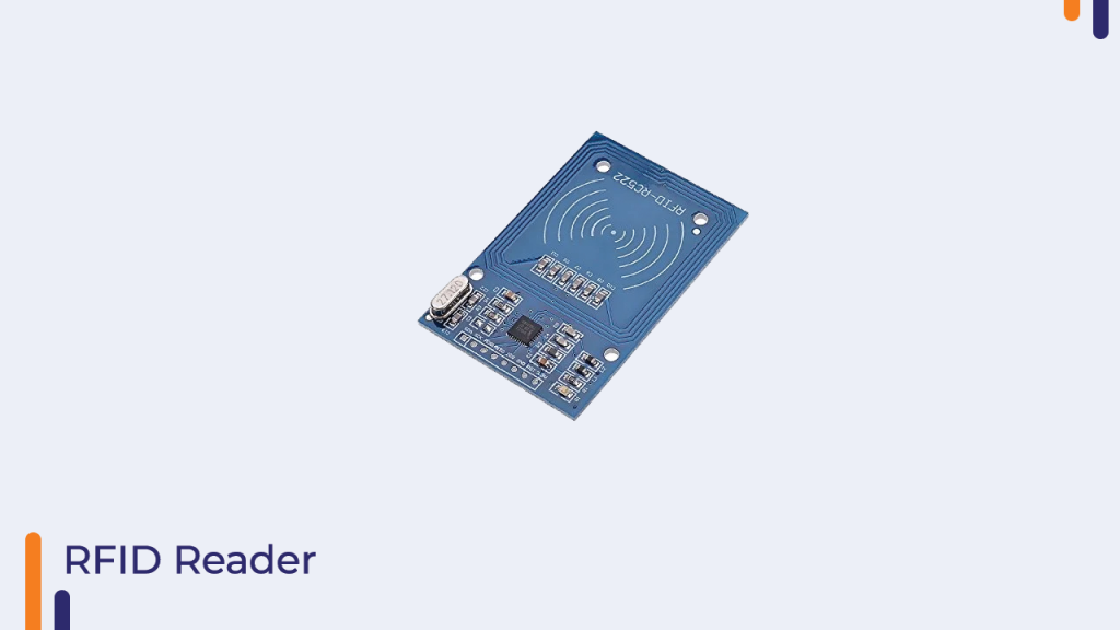
This is an RFID tag reader that reads the information on the tag.
This module includes an antenna and a radio transmitter-receiver that receives the signal sent by the RFID receiver.
RFID Tags –
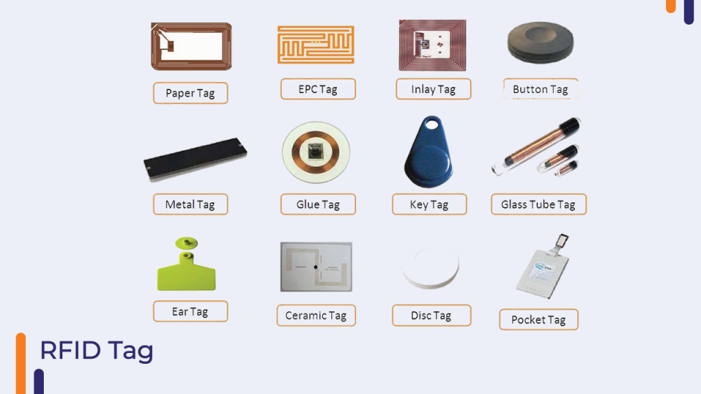
An RFID tag transmits and receives data via an antenna and a microchip, which is also known as an integrated circuit or IC. The RFID reader's microchip is programmed with whatever information the user desires.
There are two kinds of RFID tags on the market.
- Active RFID Tags
- Passive RFID Tag
Active RFID tags have an inbuilt battery that powers the RFID tag control unit, whereas passive RFID tags do not have an inbuilt battery and instead receive power from RFID readers and return information to them.
I hope you now understand RFID technology. If you have any questions, please contact us. In the following section, we will learn how to interface RFID cards with the Raspberry Pi.
MFRC-522 RC522 RFID Interfacing With Raspberry Pi
The SPI communication is used by the RFID that comes with this kit. SPI communication is a type of parallel line communication that employs four pins, which are as follows.
MOSI – Master out slave in
Miso - Master in slave out
SCK – Clock line
VCC and GND - Power Pins
The SPI communication protocol is one of the more advanced communication protocols available on standard microcontrollers.
The main benefit of using the SPI communication protocol is that we can easily connect multiple devices to the same port and form a master-slave data transfer network. The only requirement is that the device you connect to the SPI port be SPI communication protocol compatible.
So that was the fundamental introduction to SPI communication. The interfacing diagram of the RFID reader with the Raspberry Pi is shown in the image below.
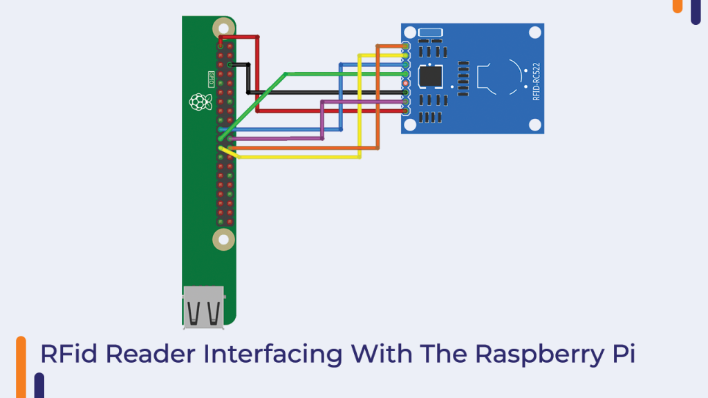
In the next part, we will talk about the programming part of the RFID card.
Python Code For RFID Card reader
Before we begin with the programming, we must first enable SPI communication on the Raspberry Pi.
Please follow the steps below to Enable SPI Communication.
- Open The Raspberry Pi Coniguration Menu. This is found under Menu > Preferences > Raspberry Pi Configuration
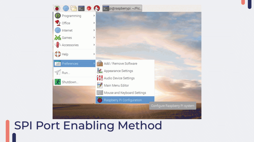
- After enabling and robooting the raspberry pi you will to install the MFRC522 library. You can install MFRC522 library by running the following command.
Sudo pip3 install mfrc522We are now all set to start working on the programming part of the RFID card.
We used two libraries in the following python code for RFID Card Reader: the GPIO library and the RFID MFC mfrc522.
The mfrc522 library is in charge of communicating with the mfrc522 RFID module. We'll use a few functions from this library to get started with the mfrc522's standard operations.
Basically, there are two operations that we usually perform with the mfrc522, which I have listed below for your convenience.
- Enrolling a New Tag
- Identifying a Tag
Enrolling a New Tag
As discussed in previous sections, each tag has a distinct identity that is used to identify the tags.
However, in order to recognise the tag, we must first store its identity, which we can do using the Python code below.
import RPi.GPIO as GPIO
from mfrc522 import SimpleMFRC522

reader = SimpleMFRC522()

try:
        text = input('New data:')
        print("Now place your tag to write")
        reader.write(text)
        print("Written")
finally:
        GPIO.cleanup()
We can use this code to read the RFID card's identity and store it on the Raspberry Pi.
Please run the above code on the Raspberry Pi. If you run into any issues or have any questions, please contact us.
Identifying A Tag
This is the second operation we perform with RFID cards. We obtain the ID of the tag after saving the ID of the cards, and when a user places that same RFID card near an RFID reader, the RFID reader reads the ID of the card and passes it to the control unit.
After receiving the ID from the reader unit, the control unit compares it to the stored ID’s and, if a match is found, the control unit returns a green signal to the main control unit; otherwise, it returns a red signal.
In this case, a green signal indicates that a match has been found, while a red signal indicates that a match has not been found.
So, if the following python code is executed on the raspberry pi, this is how the identifying procedure of the RFID Tags will take place on the controller side.
Please copy the code below and let me know if you run into any issues.
Python Code
import RPi.GPIO as GPIO
from mfrc522 import SimpleMFRC522

reader = SimpleMFRC522()

try:
        text = input('New data:')
        print("Now place your tag to write")
        reader.write(text)
        print("Written")
finally:
        GPIO.cleanup()
Please copy the code below and run it on the Raspberry PI. To run the code, go to the serial monitor and enter the filename where the code is saved, making sure to include the.py extension at the end of the file name.
After you've finished typing file name with.py extention, press the enter key.
Now, put the RFID tag over the RFID reader.
When the RFID tag is placed on the RFID reader, the raspberry receives the unique ID of the tag, which is printed on the serial monitor as we specified in the code.
If this is not happening, please check the connections; if the problem persists, please contact us.
Conclusion: We learned how to connect the RFID reader to the Raspberry Pi and how to read the data from RFID cards in this manner.
3.5 Inch Display Interfacing With The Raspberry Pi
In this section, we'll learn how to connect the 3.5-inch display to the Raspberry Pi.
We are all familiar with the use and working of an LCD display.
LCDs are made up of liquid crystals, polarizers, and color filters.
When a voltage is applied to liquid crystals, the crystals bend and allow light to pass through. As a result, it generates a pixel.If you want to learn more about the booklet, please read it to learn how the LCD works.
So that was the basic overview of the 3.5inch display module.
In the following section, we will learn how to connect the 3.5-inch display to the Raspberry Pi.
Why is A 3.5-inch-like Small Display Required?
True, a large screen is required for viewing details clearly, but this is not always the case.
We don't always use displays in some applications.
When it comes to automation and portable raspberry pi projects, however, we can only use mini-displays.
In the following section, we will discuss how to connect the display to the Raspberry Pi.
Interfacing The 3.5inch Display With The Raspberry Pi:
Unlike RFID readers, the 3.5-inch display included with this kit employs SPI communication.
That means you'll have to repeat the setup we did at the start of the RFID card reader section. We'll need to enable SPI communication first, and then run the following commands on the Raspberry Pi's terminal.
We'll go over those commands in the following section.
To begin working on the raspberry pi, you must first mount the raspberry Pi display on the raspberry pi.
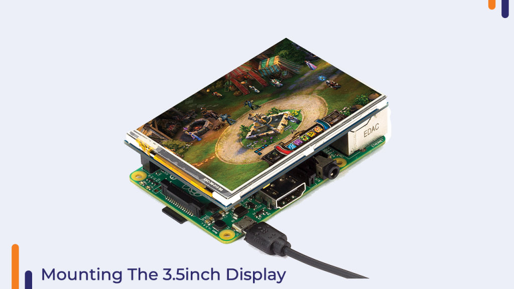
After mounting the display on the Raspberry Pi, you will need to run a few commands on the Raspberry Pi terminal, which we will go over in the following section.
How To Program The 3.5inch Display With The Raspberry Pi?
To program the 3.5inch display, we must first install the necessary drivers on the Raspberry Pi.
The drivers will be in charge of understanding the communication between the raspberry pi and the display, as well as displaying the objects on the screen.
To begin working with the display, install the following commands on the Raspberry Pi.
1.       sudo rm -rf LCD-show
2.       git clone https://github.com/goodtft/LCD-show.git
3.       chmod -R 755 LCD-show
4.       cd LCD-show/
5.       sudo ./LCD35-show
The following line of the code will remove pre-installed LCD drivers.
git clone https://github.com/goodtft/LCD-show.gitThis line of the code will download the drivers from the Github.
chmod -R 755 LCD-showThis line of code will change the permission of the files that we have downloaded from the git hub.
cd LCD-show/We are going to the folder where the driver files are stored using the above line of the code.
sudo ./LCD35-show We successfully installed the drivers on Raspberry Pi after running the above line of code.
You can now reboot the system and begin working on the Raspberry Pi 3.5inch Display.
As a result, we learned how to connect the LCD display to the Raspberry Pi in this manner.
How To Use Camera Module With The Raspberry PI?
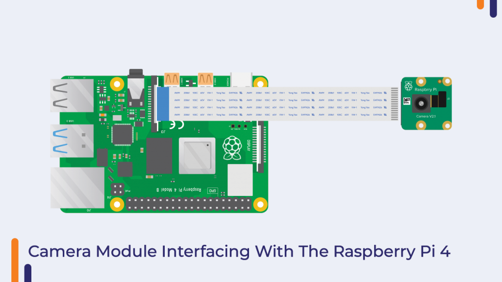
The camera module can be used in a variety of applications with the Raspberry Pi. We will learn how to use the camera module with the Raspberry Pi in this section.
You've probably seen smart surveillance systems built with Raspberry Pi boards. The images captured by these surveillance systems are captured using a camera sensor.
How to Enable Camera functionality on Raspberry Pi
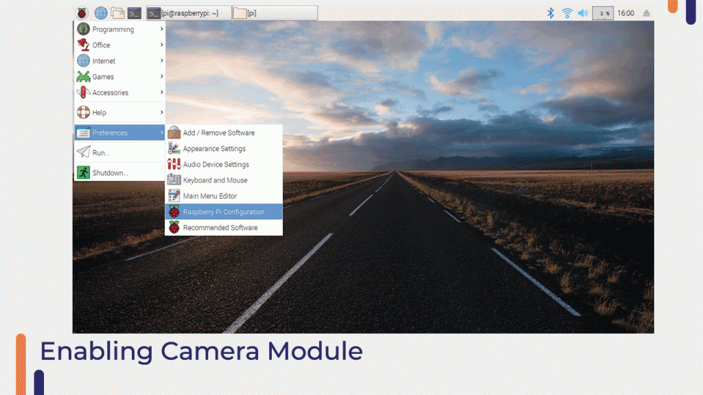
We must first enable the camera module before we can begin working with it.
Please follow the process outlined in the following image to enable the camera-port.
How To Program The Raspberry Pi?
We learned how to enable the Raspberry Pi in the previous section. In this section, we will learn how to communicate with the camera Module using Python code.
The following code can be used to programme the camera module, but it will generate errors because the required module is not present on raspberry pi.
To avoid these errors, we must install that module in the same folder as the rest of the project files.
Let's say you're working on a 1.py file and it's in a "A" folder, but when you open the terminal, it says you're in folder B.
In that case, if you want to install a new module, you must navigate to the folder using the steps below.
cd file-pathThe file-path should point to the location of your project's folder. After running the above command, you will be in the same folder where all of the files are stored, and you can now begin installing the necessary drivers.
In this case, we're going to install the files listed below in the folder. And we're installing the module on the system with the Pip install picamera command.
Pip install picameraThe camera module will be installed on the system after you run the above command on the raspberry pi terminal.
You can now run the following command to begin taking pictures with the Raspberry Pi and the camera module.
import picamera
from time import sleep
#create object for PiCamera class
camera = picamera.PiCamera()
#set resolution
camera.resolution = (1024, 768)
camera.brightness = 60
camera.start_preview()
#add text on image
camera.annotate_text = 'Hi Pi User'
sleep(5)
#store image
camera.capture('image1.jpeg')
camera.stop_preview()
Python Code Explanation
Two libraries are used in the preceding code. The first is the camera module, and the second is the time module.
The picamera module is used to communicate with the picamera sensor, and the time module is used to add the delay.
The picCamera() class is responsible for capturing images in the picamera module. Because we also want to take pictures, we created an object of that class and used a few functions of that class with the help of the object that we created in the above code.
Resolution()
As previously stated, this is a function of the piCamera class that can be used to set the image's resolution.
Brightness()
As the name implies, this function can be used to adjust the brightness of the image.
Camera.start_preview()
This function will display the preview overlay the specified resolution.
camera.stop_preview()
This function disables the function's preview overlay.
So, this was about the function that we used in the preceding code. If you have any questions, please contact us and we will gladly assist you.
In the following section, we will discuss how to connect the stepper motor to the Raspberry Pi.
Stepper Motor With The Raspberry Pi
Stepper motors, as you may know, are a type of DC motor that converts electrical pulses into step-by-step mechanical motion of the shaft.
This motor, unlike other DC motors, has a permanent magnet rotor that rotates when the stator is turned on.
The stator is built in the same way as a standard DC motor. The only difference is that this type of motor's stator has mechanical teeth. These teeth align with the teeth of the rotor after the microcontroller sends a pulse to the stator.
The microcontroller's pulse sequence allows the shaft of the motor to rotate in discrete steps. This motor requires a certain number of such pulses to complete one revolution; these pulses are also in charge of controlling the motor's speed. The frequency of the input pulses is increased to increase the rotational speed of the motor shaft.
The following picture shows the internal construction of the stepper motor.

Interfacing Stepper Motor With The Raspberry Pi
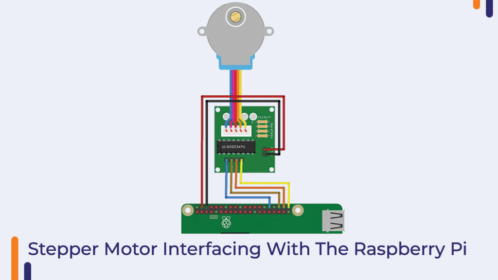
This Orange Raspberry Pi kit includes a 28byj-48 stepper motor and a UNL-2003 stepper motor driver. This motor has four pins, which must be connected to the stepper motor driver as shown in the diagram.
Please refer to the image below and make the necessary connections.
How To Program The Stepper Motor?
To communicate with the Raspberry Pi, we used the GPIO and time modules in the code below.
You can begin working with the stepper motor by copying the following code.
In this code, we simply toggle the pins.
This means that we are changing the state of the GPIO pins.
import RPi.GPIO as GPIO
import time

GPIO.setmode(GPIO.BCM)
GPIO.setwarnings(False)
coil_A_1_pin = 21 # Yellow
coil_A_2_pin = 22 # Red
coil_B_1_pin = 16 # Brown
coil_B_2_pin = 12 # Blue

# adjust if different
StepCount = 8
Seq = range(0, StepCount)
Seq[0] = [0,1,0,0]
Seq[1] = [0,1,0,1]
Seq[2] = [0,0,0,1]
Seq[3] = [1,0,0,1]
Seq[4] = [1,0,0,0]
Seq[5] = [1,0,1,0]
Seq[6] = [0,0,1,0]
Seq[7] = [0,1,1,0]

GPIO.setup(enable_pin, GPIO.OUT)
GPIO.setup(coil_A_1_pin, GPIO.OUT)
GPIO.setup(coil_A_2_pin, GPIO.OUT)
GPIO.setup(coil_B_1_pin, GPIO.OUT)
GPIO.setup(coil_B_2_pin, GPIO.OUT)

GPIO.output(enable_pin, 1)

def setStep(w1, w2, w3, w4):
    GPIO.output(coil_A_1_pin, w1)
    GPIO.output(coil_A_2_pin, w2)
    GPIO.output(coil_B_1_pin, w3)
    GPIO.output(coil_B_2_pin, w4)

def forward(delay, steps):
    for i in range(steps):
        for j in range(StepCount):
            setStep(Seq[j][0], Seq[j][1], Seq[j][2], Seq[j][3])
            time.sleep(delay)

def backwards(delay, steps):
    for i in range(steps):
        for j in reversed(range(StepCount)):
            setStep(Seq[j][0], Seq[j][1], Seq[j][2], Seq[j][3])
            time.sleep(delay)

if __name__ == '__main__':
    while True:
        delay = raw_input("Time Delay (ms)?")
        steps = raw_input("How many steps forward? ")
        forward(int(delay) / 1000.0, int(steps))
        steps = raw_input("How many steps backwards? ")
        backwards(int(delay) / 1000.0, int(steps))
Python Code Explanation For The Raspberry Pi
The pins were initialised and the modes of each pin were defined in the first section of the code.
Following that, we used a few user-defined functions.
Please take a look at the functions I've listed below.
Forward()
This function accepts two arguments. One is the delay between two functions, and the other is the number of steps we want the stepper motor to move forward.
When the function is called, the for loop written in this function is executed, and the setStep function is called and executed each time the for loop is executed.
backwards ()
This function is similar to the forward function in many ways.
The difference between these two functions is that the forward function spins the stepper motor forward while the backwards function spins the motor backwards.
setStep()
This is another function that we can use to control the spin of the motor's shaft.
This function is used to apply the received output to the motor driver's connected pins.
So, these are the functions we're using in Python code to interact with the stepper motor.
You can now run the above code in your Thorny IDE, and please let us know if you have any questions.
Heart Sensor With The Raspberry Pi
The heart rate sensor detects the living object's heart rate. It operates in a very straightforward manner. This sensor has two sides: one side has an LED and an ambient light sensor, and the other side has some circuitry.
This circuitry is in charge of amplification and noise cancellation.
The LED on the sensor's front side should be placed over a vein of our human body.
Now the LED emits light, which falls directly on the vein. Only when the heart is pumping the blood flow through the veins, so if we monitor the flow of blood, we can also monitor the heartbeats.
If blood flow is detected, the ambient light sensor will pick up lighter colours because they will be reflected by the blood; this minor change in received light is analyzed over time to determine our heartbeats.
So, this is how the heart rate sensor functions. In the following section of the blog, we will learn how to connect the heart rate sensor to the Raspberry Pi.
How To Interface The Heart Rate Sensor With The Raspberry Pi ?
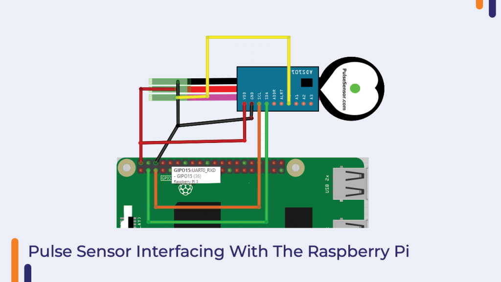
As you can see in the following image, the heart rate sensor has three pins. Out of these three pins, one is a signal pin and the other pins are power pins. Please see the following image to understand the interfacing diagram properly.
How To Program The Raspberry Pi ?
We had figured out how to connect the heart rate sensor to the Raspberry Pi up until this point. We'll talk about coding in this section of the blog.
In the preceding setup, we used the Ads Module, which converts analogue signals to digital data and sends it to the Raspberry Pi via the I2C communication channel.
As the module communicates via the I2C protocol, we must ensure that the I2C port on our Raspberry Pi board is open to accept data. If you have not yet enabled the I2C communication channel, you can do so by clicking on this link.
After you enable it, you must install the ADS1x15 python library. You can get that library by running the following command in the terminal of your Raspberry Pi OS.
sudo pip install adafruit-ads1x15# Simple heart beat reader for Raspberry pi using ADS1x15 family of ADCs and a pulse sensor - http://pulsesensor.com/.
# The code borrows heavily from Tony DiCola's examples of using ADS1x15 with
# Raspberry pi and WorldFamousElectronics's code for PulseSensor_Amped_Arduino
# Author: Udayan Kumar
# License: Public Domain
import time
# Import the ADS1x15 module.
import Adafruit_ADS1x15
if __name__ == '__main__':
adc = Adafruit_ADS1x15.ADS1015()
# initialization
GAIN = 2/3
curState = 0
thresh = 525 # mid point in the waveform
P = 512
T = 512
stateChanged = 0
sampleCounter = 0
lastBeatTime = 0
firstBeat = True
secondBeat = False
Pulse = False
IBI = 600
rate = [0]*10
amp = 100
lastTime = int(time.time()*1000)
# Main loop. use Ctrl-c to stop the code
while True:
# read from the ADC
Signal = adc.read_adc(0, gain=GAIN) #TODO: Select the correct ADC channel. I have selected A0 here
curTime = int(time.time()*1000)
sampleCounter += curTime - lastTime; # # keep track of the time in mS with this variable
lastTime = curTime
N = sampleCounter - lastBeatTime; # # monitor the time since the last beat to avoid noise
#print N, Signal, curTime, sampleCounter, lastBeatTime
## find the peak and trough of the pulse wave
if Signal < thresh and N > (IBI/5.0)*3.0 : # # avoid dichrotic noise by waiting 3/5 of last IBI
if Signal < T : # T is the trough
T = Signal; # keep track of lowest point in pulse wave
if Signal > thresh and Signal > P: # thresh condition helps avoid noise
P = Signal; # P is the peak
# keep track of highest point in pulse wave
# NOW IT'S TIME TO LOOK FOR THE HEART BEAT
# signal surges up in value every time there is a pulse
if N > 250 : # avoid high frequency noise
if (Signal > thresh) and (Pulse == False) and (N > (IBI/5.0)*3.0) :
Pulse = True; # set the Pulse flag when we think there is a pulse
IBI = sampleCounter - lastBeatTime; # measure time between beats in mS
lastBeatTime = sampleCounter; # keep track of time for next pulse
if secondBeat : # if this is the second beat, if secondBeat == TRUE
secondBeat = False; # clear secondBeat flag
for i in range(0,10): # seed the running total to get a realisitic BPM at startup
rate[i] = IBI;
if firstBeat : # if it's the first time we found a beat, if firstBeat == TRUE
firstBeat = False; # clear firstBeat flag
secondBeat = True; # set the second beat flag
continue # IBI value is unreliable so discard it
# keep a running total of the last 10 IBI values
runningTotal = 0; # clear the runningTotal variable
for i in range(0,9): # shift data in the rate array
rate[i] = rate[i+1]; # and drop the oldest IBI value
runningTotal += rate[i]; # add up the 9 oldest IBI values
rate[9] = IBI; # add the latest IBI to the rate array
runningTotal += rate[9]; # add the latest IBI to runningTotal
runningTotal /= 10; # average the last 10 IBI values
BPM = 60000/runningTotal; # how many beats can fit into a minute? that's BPM!
print ('BPM: {}'.format(BPM))
if Signal < thresh and Pulse == True : # when the values are going down, the beat is over
Pulse = False; # reset the Pulse flag so we can do it again
amp = P - T; # get amplitude of the pulse wave
thresh = amp/2 + T; # set thresh at 50% of the amplitude
P = thresh; # reset these for next time
T = thresh;
if N > 2500 : # if 2.5 seconds go by without a beat
thresh = 512; # set thresh default
P = 512; # set P default
T = 512; # set T default
lastBeatTime = sampleCounter; # bring the lastBeatTime up to date
firstBeat = True; # set these to avoid noise
secondBeat = False; # when we get the heartbeat back
print ("no beats found")
time.sleep(0.005)Conclusion: Orange Raspberry Pi Beginner Kit
In this way, we've talked about all of the components that come with this Raspberry Pi beginner kit.
Please let us know if you have any questions.


