IOT Enabled Energy Meter
Today we are going to build an IOT Enabled Energy Meter using Raspberry Pi Pico and Arduino Nano so that we can monitor energy consumed from anywhere. We’ll be using
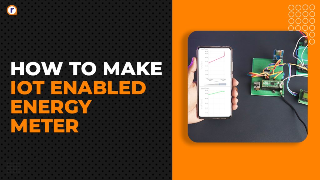
Today we are going to build an IOT Enabled Energy Meter using Raspberry Pi Pico and Arduino Nano so that we can monitor energy consumed from anywhere. We’ll be using ESP8266-01 to enable internet on our Pico so that we can send data to an external IOT service. Also, will be storing data locally for the cases when we don’t have internet connection for later reference.
Lets get started then,
Table of Contents
What is Raspberry Pi Pico and Arduino Nano ?
Raspberry Pi Pico -
The Raspberry Pi Pico series is a range of tiny, fast, and versatile development boards built on RP2040, and the microcontroller chip designed by Raspberry Pi in UK.
Some of the key features of Raspberry Pi Pico -
- Dual Core ARM Cortex-M0+ processor
- 264kB RAM
- 2 × UART, 2 × SPI controllers, 2 × I2C controllers, 16 × PWM channels
- Supported input voltage 1.8–5.5V DC
- Accurate on-chip clock
- Temperature sensor
Arduino Nano -
Arduino Nano is a small, complete, and breadboard-friendly board based on the ATmega328. It has more or less the same functionality of the Arduino Duemilanove, but in a different package. It lacks only a DC power jack, and works with a Mini-B USB cable instead of a standard one.
Some of the key features of Arduino Nano -
- ATmega328
- 2kB RAM
- Supported input voltage 4–12V DC
- 1× UART, 1× I2C controllers, 6 × PWM channels
Hardware Requirements of this Project -
- Raspberry Pi Pico
- Arduino Nano
- 1602 LCD Display with I2C adapter
- ESP8266-01
- SD Card Module and 16GB SD Card
- 4 Channel Bi-Directional Logic Converter
- Prototype Board
- Main Terminal
- Small Terminal
- 5v 1A Power Supply
- Headers Male and Female
- Jumper Cables
- Button
- Wires - Copper 1.2mm diameter
Software Requirements of this Project -
- Thonny IDE
- Arduino IDE
- LCD libraries for Pi Pico.
- SD Card libraries for Pi Pico
- Ubidots Dashboard
Now, lets move on to setting up of IDE and Libraries
Prerequisites and setting up -
Download latest Thonny IDE for your system and install it. Similarly download or get Arduino IDE from their website/windows store.
After installing both Thonny and Arduino IDE, open them up
Libraries / Firmware-
We gonna need the libraries for the LCD and the SD card module. So, open Thonny IDE and connect the Raspberry Pi Pico. Wait for some time for the computer to recognize the Pi Pico. After it recognizes, look at the bottom corner of the IDE for the python version, click on there and this window shall come up -
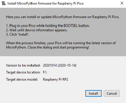
Press Install button, and wait it finishes updating the firmware and stuffs on the Raspberry Pi Pico.
Ubidots Dashboard -
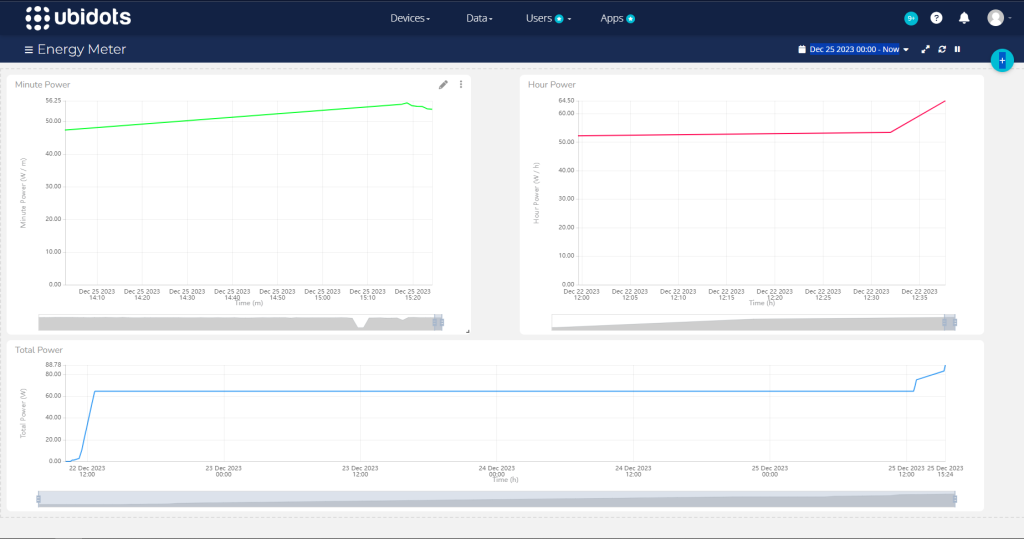
Visit Ubidots.com and login/sign up if you don't have an account. After Making an account, go to devices. Click on your profile -> API Credentials. Copy the token, and replace the token in main.py later. After you've followed the circuit diagram, and powered up the circuit. A new device should pop up in the devices tab. From there you can add graphs in dashboard tab to show the data streams that your device is receiving.
Circuit Diagram and Hardware Interfacing -
Circuit Diagram -

Hardware Interfacing -
Arduino Nano -
|
Arduino Nano Pins |
Logic Converter |
|
+Ve |
HV |
|
-Ve |
GND |
|
A4 |
H3 |
|
A5 |
H4 |
Raspberry Pi Pico -
|
Raspberry Pi Pico |
Logic Converter |
|
+3.3V |
LV |
|
GND |
GND |
|
Pin 9 |
H1 |
|
Pin 10 |
H2 |
ESP8266-01 -
|
ESP8266-01 |
Pi Pico |
|
+3.3V |
+3.3 OUT |
|
EN |
+3.3 OUT |
|
GND |
GND |
|
TX |
Pin 22 |
|
RX |
Pin 21 |
SD Card Module -
|
SD Card Module |
Pi Pico |
|
VCC |
VSYS |
|
GND |
GND |
|
CS |
GP 13 |
|
SCK |
GP 10 |
|
MOSI |
GP 11 |
|
MISO |
GP 12 |
Coding -
Copy the following code and pat it into Arduino IDE and after connecting Arduino Nano to your pc. Before you upload the code, make sure to select the correct port on which Arduino Nano is connected.
It should be automatic in newer IDE's, but in case it didn't auto select the PORT, assign the correct port in Tools section of the IDE.
#include <Wire.h>

float power,x,y;
int i=0,temp=0;
char a[5];

int decimalPrecision = 2;
int VoltageAnalogInputPin = A1;
float voltageSampleRead  = 0;
float voltageLastSample  = 0;
float voltageSampleSum   = 0;
float voltageSampleCount = 0;
float voltageMean ;
float RMSVoltageMean ;
float adjustRMSVoltageMean;
float FinalRMSVoltage;
float voltageOffset1 =0.00 ;
float voltageOffset2 = 0.00;

#define SAMPLES 300
#define ACS_Pin A0
float High_peak,Low_peak;
float Amps_Peak_Peak, Amps_RMS;

float voltage(){
  while(voltageSampleCount<1000){
    if(micros() >= voltageLastSample + 1000) {
      voltageSampleRead = (analogRead(VoltageAnalogInputPin)-512) + voltageOffset1;
      voltageSampleSum = voltageSampleSum + sq(voltageSampleRead);
      voltageSampleCount = voltageSampleCount + 1;
      voltageLastSample = micros();
    }
  }

  if(voltageSampleCount == 1000){
    voltageMean = voltageSampleSum / voltageSampleCount;
    RMSVoltageMean = (sqrt(voltageMean)) * 1.5;
    adjustRMSVoltageMean = RMSVoltageMean + voltageOffset2;
    FinalRMSVoltage = RMSVoltageMean + voltageOffset2;

    if(FinalRMSVoltage<=100){
      FinalRMSVoltage=0;
    }
    if(FinalRMSVoltage>=270){
      FinalRMSVoltage=0;
    }

    Serial.print("Voltage : ");
    Serial.print(FinalRMSVoltage,decimalPrecision);
    Serial.print("V");
    voltageSampleSum=0;
    voltageSampleCount=0;
  }
  //return(FinalRMSVoltage,decimalPrecision);
  return FinalRMSVoltage;
}

float current(){
  int cnt;
  High_peak = 0;
  Low_peak = 1024;

  for(cnt=0 ; cnt<SAMPLES ; cnt++){
    float ACS_Value = analogRead(ACS_Pin);
    if(ACS_Value > High_peak)
      High_peak = ACS_Value;

    if(ACS_Value < Low_peak)
      Low_peak = ACS_Value;
  }

  Amps_Peak_Peak = High_peak - Low_peak;
  Amps_RMS = Amps_Peak_Peak * 0.103 * 0.0134;

  if( Amps_RMS <= 0.10){
    Amps_RMS = 0;
  }

  Serial.print("  Amps: ");
  Serial.print(Amps_RMS);
  Serial.println("A");
  return Amps_RMS;
}

void requestEvent(){
  temp=power*100;
  for(int i=0;i<5;i++)  {
    a[i]=temp%10;
    temp=temp/10;
  }
  for(int i=0;i<5;i++)
    Wire.write(a[i]);
}

void setup(){
  Serial.begin(9600);
  Wire.begin(9);
  Wire.onRequest(requestEvent);

  pinMode(ACS_Pin,INPUT);

  pinMode(5,OUTPUT);
  pinMode(6,OUTPUT);
  digitalWrite(5,HIGH);
  digitalWrite(6,HIGH);
  delay(500);
}

void loop(){
  x=voltage();
  y=current();
  power = x * y;
  Serial.println(power);
  delay(500);
}
Now for the Raspberry Pi Pico -
Copy the below code and save it onto Pico by naming it main.py
Why you may ask? Because when Pico gets powered, it automatically runs file named main.py without needing it to connect to IDE/PC.
from machine import Pin, I2C, SPI, UART, ADC
from pico_i2c_api import I2cLcd
from time import sleep

import sdcard
import _thread
import uasyncio
import uos
import sys

adc = ADC(0)
wifi_status = 0

SSID = "ROBU_TEST"
PASSWORD = "12345678"
TOKEN = "Your Token here"
DEVICE_LABEL="pipico"
USER_AGENT="randomstring@12345"

i2c=I2C(0,sda=Pin(0),scl=Pin(1),freq=400000)
power=I2C(1,sda=Pin(6),scl=Pin(7),freq=100000)
uart = UART(0,115200,tx=Pin(16), rx=Pin(17))
#print(hex(i2c.scan()[0]))

addr = 0
lcd = 0
wifi_logo = bytearray([0b01110,0b10001,0b00000,0b01110,0b10001,0b00100,0b00000,0b00000])

def arduino_assign():
    try:
        global addr
        addr=power.scan()[0]
        print("Arduino OK")
    except:
        raise RuntimeError("Cant Communicate with arduino")


def lcd_assign():
    try:
        global lcd
        lcd=I2cLcd(i2c,0x27,2,16)
        print("LCD OK")
    except:
        raise RuntimeError("Cant Communicate with LCD")

def sd_card():
    try:
        cs = machine.Pin(13, machine.Pin.OUT)
        spi = machine.SPI(1,baudrate=1000000,polarity=0,phase=0,bits=8,firstbit=machine.SPI.MSB,sck=machine.Pin(10),mosi=machine.Pin(11),miso=machine.Pin(12))
        sd=sdcard.SDCard(spi,cs)
        vfs = uos.VfsFat(sd)
        uos.mount(vfs, "/sd")
        print("SD Card OK")
    except:
        raise RuntimeError("Something Wrong with SD Card")


def wifi_is_connected_response(command):
    recv=bytes()
    while uart.any()>0:
        recv+=uart.read(1)
    res = recv
    return res

def wifi_con():
    global wifi_status, SSID
    send = "AT+CWJAP?"
    uart.write(send+'\r\n')
    res=wifi_is_connected_response(send)
    sleep(4)
    if SSID in res:
        wifi_status = 1
    else:
        wifi_status = 0

def wifi_check():
    global wifi_status, SSID

    send = "AT+CWJAP?"
    uart.write(send+'\r\n')
    res=wifi_is_connected_response(send)

    if SSID in res:
        wifi_status = 1
    else:
        wifi_status = 0


def connect_wifi(ssid, password):
    try:
        send = "AT+CWJAP?"
        uart.write(send+'\r\n')
        res=wifi_is_connected_response(send)
        while ssid not in res:
            send = "AT+CWJAP=\""+ssid+"\",\""+password+"\""
            uart.write(send+'\r\n')

            print("Connecting to Wifi")
            lcd.clear()
            lcd.move_to(1,0)
            lcd.putstr("Connecting  to")
            lcd.move_to(6,1)
            lcd.putstr("Wifi")

            send = "AT+CWJAP?"
            uart.write(send+'\r\n')
            res=wifi_is_connected_response(send)
            sleep(4)
        lcd.clear()
        print("Connected to Wifi")
    except:
        raise RuntimeError("Something Wrong with ESP8266")


try:
    arduino_assign()
    lcd_assign()
    sd_card()
    connect_wifi(SSID, PASSWORD)
    wifi_con()

except RuntimeError as e:
    print(f"Error : {e}" )
    sys.exit()

lcd_mode=0
lcd.backlight_off()

total_power=0.00
hour_power=0.00
minute_power=0.00

temp_minute=[]
temp_minute_count=0
temp_hour=[]
temp_hour_count=0


def sendtcp(value,VARIABLE_LABEL):
    send='AT+CIPSTART="TCP","industrial.api.ubidots.com",9012'
    uart.write(send+'\r\n')
    sleep(2)

    payload= DEVICE_LABEL+"=>"+VARIABLE_LABEL+":"+str(value)
    payload_length= len(payload)

    req_length = 11
    req_length+= len(USER_AGENT+TOKEN+str(payload_length)+payload)

    send="AT+CIPSEND="+str(req_length)
    uart.write(send+'\r\n')
    sleep(0.6)

    send=USER_AGENT+"|POST|"+TOKEN+"|"+payload+"|end"
    #print("request sent: "+USER_AGENT+"|POST|"+TOKEN+"|"+payload+"|end")      #Debug
    uart.write(send+'\r\n')
    sleep(0.6)

    print("Data sent: "+payload)


def save_total_pow(x):                                                         #TO SAVE TOTAL_POWER DATA TO TOTAL_POWER FILE
    with open("/sd/total_power.txt", 'w') as file:
        file.write(str(x)+"\r\n")
        file.close()

def save_hour_pow(x):                                                          #TO SAVE HOUR_POWER DATA TO HOUR_POWER FILE
    with open("/sd/hour_power.txt", 'a') as file:
        file.write(str(x)+"\r\n")
        file.close()

def save_minute_pow(x):                                                        #TO SAVE MINUTE_POWER DATA TO MINUTE_POWER FILE
    with open("/sd/minute_power.txt", 'a') as file:
        file.write(str(x)+"\r\n")
        file.close()


async def read_arduino():                                                           #TO GET DATA FROM ARDUINO
    second_data=0.00
    a= power.readfrom(addr,5)
    b=(a[4]*100+a[3]*10+a[2]+((a[1]*10+a[0])/100))
    second_data = second_data + float(b)
    return second_data


async def calc_minute(temp_min):                                                            #TO CALCULATE MINUTE DATA
    global minute_power, total_power
    for i in range(0,len(temp_min)):
        minute_power = temp_min[i] + minute_power

    minute_power = minute_power / len(temp_min)
    save_minute_pow(minute_power)
    save_total_pow(total_power + minute_power/60)
    return minute_power

async def calc_hour(temp_hr):                                                              #TO CALCULATE HOUR DATA
    global hour_power
    for i in range(0,len(temp_hr)):
        hour_power = temp_hr[i] + hour_power

    hour_power = hour_power / len(temp_hr)
    save_hour_pow(hour_power)
    return hour_power


async def button_cycle():
    global lcd_mode
    while True:
        adc_value = adc.read_u16()
        if adc_value < 500:
            lcd_mode = lcd_mode + 1
            lcd.backlight_on()
            if lcd_mode < 3:
                await uasyncio.sleep(2)
        if lcd_mode > 2:
            lcd_mode = 0
            await uasyncio.sleep(2)
        lcd.backlight_off()
        await uasyncio.sleep(0.1)


async def print_lcd():                                                           #TO PRINT ON LCD
    global total_power, minute_power, hour_power, lcd_mode
    while True:
        if lcd_mode == 0:
            lcd.clear()
            lcd.move_to(0,0)
            lcd.putstr(str(int(total_power)))
            lcd.move_to(14,1)
            lcd.putstr(" W")
            if wifi_status == 1:
                lcd.custom_char(0, wifi_logo)
                lcd.move_to(0, 1)
                lcd.putchar(chr(0))
        elif lcd_mode == 1:
            lcd.clear()
            lcd.move_to(0,0)
            lcd.putstr(str(int(minute_power)))
            lcd.move_to(13,1)
            lcd.putstr("W/m")
            if wifi_status == 1:
                lcd.custom_char(0, wifi_logo)
                lcd.move_to(0, 1)
                lcd.putchar(chr(0))
        elif lcd_mode == 2:
            lcd.clear()
            lcd.move_to(0,0)
            lcd.putstr(str(int(hour_power)))
            lcd.move_to(13,1)
            lcd.putstr("W/h")
            if wifi_status == 1:
                lcd.custom_char(0, wifi_logo)
                lcd.move_to(0, 1)
                lcd.putchar(chr(0))
        await uasyncio.sleep(0.5)


def read_file():                                                              #TO READ BACK TOTAL POWER AFTER POWER CUTS
    global total_power
    with open("/sd/total_power.txt", "r") as file:
        data = file.read()
        total_power = float(data)
        file.close()


async def main():
    global temp_minute, temp_minute_count, temp_hour, temp_hour_count, minute_power, hour_power, total_power

    read_file()

    uasyncio.create_task(print_lcd())
    uasyncio.create_task(button_cycle())

    while True:
        s_power = await read_arduino()
        temp_minute.append(s_power)
        temp_minute_count = temp_minute_count + 1

        if temp_minute_count == 60:
            minute_power = await calc_minute(temp_minute)
            temp_hour.append(minute_power)
            temp_hour_count = temp_hour_count + 1
            total_power = total_power + minute_power/60

            sendtcp(minute_power,f'Minute Power')
            sendtcp(total_power,f'Total Power')

            wifi_check()
            temp_minute.clear()
            temp_minute_count = 0

        if temp_hour_count == 60:
            hour_power = await calc_hour(temp_hour)

            sendtcp(hour_power,f'Hour Power')

            temp_hour.clear()
            temp_hour_count = 0

        await uasyncio.sleep(1)


uasyncio.run(main())
And also same the below file named lcd_api.py
import time

class LcdApi:

    # Implements the API for talking with HD44780 compatible character LCDs.
    # This class only knows what commands to send to the LCD, and not how to get
    # them to the LCD.
    #
    # It is expected that a derived class will implement the hal_xxx functions.
    #
    # The following constant names were lifted from the avrlib lcd.h header file,
    # with bit numbers changed to bit masks.

    # HD44780 LCD controller command set
    LCD_CLR             = 0x01  # DB0: clear display
    LCD_HOME            = 0x02  # DB1: return to home position

    LCD_ENTRY_MODE      = 0x04  # DB2: set entry mode
    LCD_ENTRY_INC       = 0x02  # DB1: increment
    LCD_ENTRY_SHIFT     = 0x01  # DB0: shift

    LCD_ON_CTRL         = 0x08  # DB3: turn lcd/cursor on
    LCD_ON_DISPLAY      = 0x04  # DB2: turn display on
    LCD_ON_CURSOR       = 0x02  # DB1: turn cursor on
    LCD_ON_BLINK        = 0x01  # DB0: blinking cursor

    LCD_MOVE            = 0x10  # DB4: move cursor/display
    LCD_MOVE_DISP       = 0x08  # DB3: move display (0-> move cursor)
    LCD_MOVE_RIGHT      = 0x04  # DB2: move right (0-> left)

    LCD_FUNCTION        = 0x20  # DB5: function set
    LCD_FUNCTION_8BIT   = 0x10  # DB4: set 8BIT mode (0->4BIT mode)
    LCD_FUNCTION_2LINES = 0x08  # DB3: two lines (0->one line)
    LCD_FUNCTION_10DOTS = 0x04  # DB2: 5x10 font (0->5x7 font)
    LCD_FUNCTION_RESET  = 0x30  # See "Initializing by Instruction" section

    LCD_CGRAM           = 0x40  # DB6: set CG RAM address
    LCD_DDRAM           = 0x80  # DB7: set DD RAM address

    LCD_RS_CMD          = 0
    LCD_RS_DATA         = 1

    LCD_RW_WRITE        = 0
    LCD_RW_READ         = 1

    def __init__(self, num_lines, num_columns):
        self.num_lines = num_lines
        if self.num_lines > 4:
            self.num_lines = 4
        self.num_columns = num_columns
        if self.num_columns > 40:
            self.num_columns = 40
        self.cursor_x = 0
        self.cursor_y = 0
        self.implied_newline = False
        self.backlight = True
        self.display_off()
        self.backlight_on()
        self.clear()
        self.hal_write_command(self.LCD_ENTRY_MODE | self.LCD_ENTRY_INC)
        self.hide_cursor()
        self.display_on()

    def clear(self):
        # Clears the LCD display and moves the cursor to the top left corner
        self.hal_write_command(self.LCD_CLR)
        self.hal_write_command(self.LCD_HOME)
        self.cursor_x = 0
        self.cursor_y = 0

    def show_cursor(self):
        # Causes the cursor to be made visible
        self.hal_write_command(self.LCD_ON_CTRL | self.LCD_ON_DISPLAY |
                               self.LCD_ON_CURSOR)

    def hide_cursor(self):
        # Causes the cursor to be hidden
        self.hal_write_command(self.LCD_ON_CTRL | self.LCD_ON_DISPLAY)

    def blink_cursor_on(self):
        # Turns on the cursor, and makes it blink
        self.hal_write_command(self.LCD_ON_CTRL | self.LCD_ON_DISPLAY |
                               self.LCD_ON_CURSOR | self.LCD_ON_BLINK)

    def blink_cursor_off(self):
        # Turns on the cursor, and makes it no blink (i.e. be solid)
        self.hal_write_command(self.LCD_ON_CTRL | self.LCD_ON_DISPLAY |
                               self.LCD_ON_CURSOR)

    def display_on(self):
        # Turns on (i.e. unblanks) the LCD
        self.hal_write_command(self.LCD_ON_CTRL | self.LCD_ON_DISPLAY)

    def display_off(self):
        # Turns off (i.e. blanks) the LCD
        self.hal_write_command(self.LCD_ON_CTRL)

    def backlight_on(self):
        # Turns the backlight on.

        # This isn't really an LCD command, but some modules have backlight
        # controls, so this allows the hal to pass through the command.
        self.backlight = True
        self.hal_backlight_on()

    def backlight_off(self):
        # Turns the backlight off.

        # This isn't really an LCD command, but some modules have backlight
        # controls, so this allows the hal to pass through the command.
        self.backlight = False
        self.hal_backlight_off()

    def move_to(self, cursor_x, cursor_y):
        # Moves the cursor position to the indicated position. The cursor
        # position is zero based (i.e. cursor_x == 0 indicates first column).
        self.cursor_x = cursor_x
        self.cursor_y = cursor_y
        addr = cursor_x & 0x3f
        if cursor_y & 1:
            addr += 0x40    # Lines 1 & 3 add 0x40
        if cursor_y & 2:    # Lines 2 & 3 add number of columns
            addr += self.num_columns
        self.hal_write_command(self.LCD_DDRAM | addr)

    def putchar(self, char):
        # Writes the indicated character to the LCD at the current cursor
        # position, and advances the cursor by one position.
        if char == '\n':
            if self.implied_newline:
                # self.implied_newline means we advanced due to a wraparound,
                # so if we get a newline right after that we ignore it.
                pass
            else:
                self.cursor_x = self.num_columns
        else:
            self.hal_write_data(ord(char))
            self.cursor_x += 1
        if self.cursor_x >= self.num_columns:
            self.cursor_x = 0
            self.cursor_y += 1
            self.implied_newline = (char != '\n')
        if self.cursor_y >= self.num_lines:
            self.cursor_y = 0
        self.move_to(self.cursor_x, self.cursor_y)

    def putstr(self, string):
        # Write the indicated string to the LCD at the current cursor
        # position and advances the cursor position appropriately.
        for char in string:
            self.putchar(char)

    def custom_char(self, location, charmap):
        # Write a character to one of the 8 CGRAM locations, available
        # as chr(0) through chr(7).
        location &= 0x7
        self.hal_write_command(self.LCD_CGRAM | (location << 3))
        self.hal_sleep_us(40)
        for i in range(8):
            self.hal_write_data(charmap[i])
            self.hal_sleep_us(40)
        self.move_to(self.cursor_x, self.cursor_y)

    def hal_backlight_on(self):
        # Allows the hal layer to turn the backlight on.
        # If desired, a derived HAL class will implement this function.
        pass

    def hal_backlight_off(self):
        # Allows the hal layer to turn the backlight off.
        # If desired, a derived HAL class will implement this function.
        pass

    def hal_write_command(self, cmd):
        # Write a command to the LCD.
        # It is expected that a derived HAL class will implement this function.
        raise NotImplementedError

    def hal_write_data(self, data):
        # Write data to the LCD.
        # It is expected that a derived HAL class will implement this function.
        raise NotImplementedError

    def hal_sleep_us(self, usecs):
        # Sleep for some time (given in microseconds)
        time.sleep_us(usecs)
Similarly, this code as pico_i2c_api.py
import utime
import gc

from lcd_api import LcdApi
from machine import I2C

# PCF8574 pin definitions
MASK_RS = 0x01       # P0
MASK_RW = 0x02       # P1
MASK_E  = 0x04       # P2

SHIFT_BACKLIGHT = 3  # P3
SHIFT_DATA      = 4  # P4-P7

class I2cLcd(LcdApi):

    #Implements a HD44780 character LCD connected via PCF8574 on I2C

    def __init__(self, i2c, i2c_addr, num_lines, num_columns):
        self.i2c = i2c
        self.i2c_addr = i2c_addr
        self.i2c.writeto(self.i2c_addr, bytes([0]))
        utime.sleep_ms(20)   # Allow LCD time to powerup
        # Send reset 3 times
        self.hal_write_init_nibble(self.LCD_FUNCTION_RESET)
        utime.sleep_ms(5)    # Need to delay at least 4.1 msec
        self.hal_write_init_nibble(self.LCD_FUNCTION_RESET)
        utime.sleep_ms(1)
        self.hal_write_init_nibble(self.LCD_FUNCTION_RESET)
        utime.sleep_ms(1)
        # Put LCD into 4-bit mode
        self.hal_write_init_nibble(self.LCD_FUNCTION)
        utime.sleep_ms(1)
        LcdApi.__init__(self, num_lines, num_columns)
        cmd = self.LCD_FUNCTION
        if num_lines > 1:
            cmd |= self.LCD_FUNCTION_2LINES
        self.hal_write_command(cmd)
        gc.collect()

    def hal_write_init_nibble(self, nibble):
        # Writes an initialization nibble to the LCD.
        # This particular function is only used during initialization.
        byte = ((nibble >> 4) & 0x0f) << SHIFT_DATA
        self.i2c.writeto(self.i2c_addr, bytes([byte | MASK_E]))
        self.i2c.writeto(self.i2c_addr, bytes([byte]))
        gc.collect()

    def hal_backlight_on(self):
        # Allows the hal layer to turn the backlight on
        self.i2c.writeto(self.i2c_addr, bytes([1 << SHIFT_BACKLIGHT]))
        gc.collect()

    def hal_backlight_off(self):
        #Allows the hal layer to turn the backlight off
        self.i2c.writeto(self.i2c_addr, bytes([0]))
        gc.collect()

    def hal_write_command(self, cmd):
        # Write a command to the LCD. Data is latched on the falling edge of E.
        byte = ((self.backlight << SHIFT_BACKLIGHT) |
                (((cmd >> 4) & 0x0f) << SHIFT_DATA))
        self.i2c.writeto(self.i2c_addr, bytes([byte | MASK_E]))
        self.i2c.writeto(self.i2c_addr, bytes([byte]))
        byte = ((self.backlight << SHIFT_BACKLIGHT) |
                ((cmd & 0x0f) << SHIFT_DATA))
        self.i2c.writeto(self.i2c_addr, bytes([byte | MASK_E]))
        self.i2c.writeto(self.i2c_addr, bytes([byte]))
        if cmd <= 3:
            # The home and clear commands require a worst case delay of 4.1 msec
            utime.sleep_ms(5)
        gc.collect()

    def hal_write_data(self, data):
        # Write data to the LCD. Data is latched on the falling edge of E.
        byte = (MASK_RS |
                (self.backlight << SHIFT_BACKLIGHT) |
                (((data >> 4) & 0x0f) << SHIFT_DATA))
        self.i2c.writeto(self.i2c_addr, bytes([byte | MASK_E]))
        self.i2c.writeto(self.i2c_addr, bytes([byte]))
        byte = (MASK_RS |
                (self.backlight << SHIFT_BACKLIGHT) |
                ((data & 0x0f) << SHIFT_DATA))
        self.i2c.writeto(self.i2c_addr, bytes([byte | MASK_E]))
        self.i2c.writeto(self.i2c_addr, bytes([byte]))
        gc.collect()
Also, not forgetting the library required for the SD card module. Save it by naming it sdcard.py
"""
MicroPython driver for SD cards using SPI bus.
Requires an SPI bus and a CS pin.  Provides readblocks and writeblocks
methods so the device can be mounted as a filesystem.
Example usage on pyboard:
    import pyb, sdcard, os
    sd = sdcard.SDCard(pyb.SPI(1), pyb.Pin.board.X5)
    pyb.mount(sd, '/sd2')
    os.listdir('/')
Example usage on ESP8266:
    import machine, sdcard, os
    sd = sdcard.SDCard(machine.SPI(1), machine.Pin(15))
    os.mount(sd, '/sd')
    os.listdir('/')
"""

from micropython import const
import time


_CMD_TIMEOUT = const(100)

_R1_IDLE_STATE = const(1 << 0)
# R1_ERASE_RESET = const(1 << 1)
_R1_ILLEGAL_COMMAND = const(1 << 2)
# R1_COM_CRC_ERROR = const(1 << 3)
# R1_ERASE_SEQUENCE_ERROR = const(1 << 4)
# R1_ADDRESS_ERROR = const(1 << 5)
# R1_PARAMETER_ERROR = const(1 << 6)
_TOKEN_CMD25 = const(0xFC)
_TOKEN_STOP_TRAN = const(0xFD)
_TOKEN_DATA = const(0xFE)


class SDCard:
    def __init__(self, spi, cs):
        self.spi = spi
        self.cs = cs

        self.cmdbuf = bytearray(6)
        self.dummybuf = bytearray(512)
        self.tokenbuf = bytearray(1)
        for i in range(512):
            self.dummybuf[i] = 0xFF
        self.dummybuf_memoryview = memoryview(self.dummybuf)

        # initialise the card
        self.init_card()

    def init_spi(self, baudrate):
        try:
            master = self.spi.MASTER
        except AttributeError:
            # on ESP8266
            self.spi.init(baudrate=baudrate, phase=0, polarity=0)
        else:
            # on pyboard
            self.spi.init(master, baudrate=baudrate, phase=0, polarity=0)

    def init_card(self):
        # init CS pin
        self.cs.init(self.cs.OUT, value=1)

        # init SPI bus; use low data rate for initialisation
        self.init_spi(100000)

        # clock card at least 100 cycles with cs high
        for i in range(16):
            self.spi.write(b"\xff")

        # CMD0: init card; should return _R1_IDLE_STATE (allow 5 attempts)
        for _ in range(5):
            if self.cmd(0, 0, 0x95) == _R1_IDLE_STATE:
                break
        else:
            raise OSError("no SD card")

        # CMD8: determine card version
        r = self.cmd(8, 0x01AA, 0x87, 4)
        if r == _R1_IDLE_STATE:
            self.init_card_v2()
        elif r == (_R1_IDLE_STATE | _R1_ILLEGAL_COMMAND):
            self.init_card_v1()
        else:
            raise OSError("couldn't determine SD card version")

        # get the number of sectors
        # CMD9: response R2 (R1 byte + 16-byte block read)
        if self.cmd(9, 0, 0, 0, False) != 0:
            raise OSError("no response from SD card")
        csd = bytearray(16)
        self.readinto(csd)
        if csd[0] & 0xC0 == 0x40:  # CSD version 2.0
            self.sectors = ((csd[8] << 8 | csd[9]) + 1) * 1024
        elif csd[0] & 0xC0 == 0x00:  # CSD version 1.0 (old, <=2GB)
            c_size = csd[6] & 0b11 | csd[7] << 2 | (csd[8] & 0b11000000) << 4
            c_size_mult = ((csd[9] & 0b11) << 1) | csd[10] >> 7
            self.sectors = (c_size + 1) * (2 ** (c_size_mult + 2))
        else:
            raise OSError("SD card CSD format not supported")
        # print('sectors', self.sectors)

        # CMD16: set block length to 512 bytes
        if self.cmd(16, 512, 0) != 0:
            raise OSError("can't set 512 block size")

        # set to high data rate now that it's initialised
        self.init_spi(1320000)

    def init_card_v1(self):
        for i in range(_CMD_TIMEOUT):
            self.cmd(55, 0, 0)
            if self.cmd(41, 0, 0) == 0:
                self.cdv = 512
                # print("[SDCard] v1 card")
                return
        raise OSError("timeout waiting for v1 card")

    def init_card_v2(self):
        for i in range(_CMD_TIMEOUT):
            time.sleep_ms(50)
            self.cmd(58, 0, 0, 4)
            self.cmd(55, 0, 0)
            if self.cmd(41, 0x40000000, 0) == 0:
                self.cmd(58, 0, 0, 4)
                self.cdv = 1
                # print("[SDCard] v2 card")
                return
        raise OSError("timeout waiting for v2 card")

    def cmd(self, cmd, arg, crc, final=0, release=True, skip1=False):
        self.cs(0)

        # create and send the command
        buf = self.cmdbuf
        buf[0] = 0x40 | cmd
        buf[1] = arg >> 24
        buf[2] = arg >> 16
        buf[3] = arg >> 8
        buf[4] = arg
        buf[5] = crc
        self.spi.write(buf)

        if skip1:
            self.spi.readinto(self.tokenbuf, 0xFF)

        # wait for the response (response[7] == 0)
        for i in range(_CMD_TIMEOUT):
            self.spi.readinto(self.tokenbuf, 0xFF)
            response = self.tokenbuf[0]
            if not (response & 0x80):
                # this could be a big-endian integer that we are getting here
                for j in range(final):
                    self.spi.write(b"\xff")
                if release:
                    self.cs(1)
                    self.spi.write(b"\xff")
                return response

        # timeout
        self.cs(1)
        self.spi.write(b"\xff")
        return -1

    def readinto(self, buf):
        self.cs(0)

        # read until start byte (0xff)
        for i in range(_CMD_TIMEOUT):
            self.spi.readinto(self.tokenbuf, 0xFF)
            if self.tokenbuf[0] == _TOKEN_DATA:
                break
            time.sleep_ms(1)
        else:
            self.cs(1)
            raise OSError("timeout waiting for response")

        # read data
        mv = self.dummybuf_memoryview
        if len(buf) != len(mv):
            mv = mv[: len(buf)]
        self.spi.write_readinto(mv, buf)

        # read checksum
        self.spi.write(b"\xff")
        self.spi.write(b"\xff")

        self.cs(1)
        self.spi.write(b"\xff")

    def write(self, token, buf):
        self.cs(0)

        # send: start of block, data, checksum
        self.spi.read(1, token)
        self.spi.write(buf)
        self.spi.write(b"\xff")
        self.spi.write(b"\xff")

        # check the response
        if (self.spi.read(1, 0xFF)[0] & 0x1F) != 0x05:
            self.cs(1)
            self.spi.write(b"\xff")
            return

        # wait for write to finish
        while self.spi.read(1, 0xFF)[0] == 0:
            pass

        self.cs(1)
        self.spi.write(b"\xff")

    def write_token(self, token):
        self.cs(0)
        self.spi.read(1, token)
        self.spi.write(b"\xff")
        # wait for write to finish
        while self.spi.read(1, 0xFF)[0] == 0x00:
            pass

        self.cs(1)
        self.spi.write(b"\xff")

    def readblocks(self, block_num, buf):
        nblocks = len(buf) // 512
        assert nblocks and not len(buf) % 512, "Buffer length is invalid"
        if nblocks == 1:
            # CMD17: set read address for single block
            if self.cmd(17, block_num * self.cdv, 0, release=False) != 0:
                # release the card
                self.cs(1)
                raise OSError(5)  # EIO
            # receive the data and release card
            self.readinto(buf)
        else:
            # CMD18: set read address for multiple blocks
            if self.cmd(18, block_num * self.cdv, 0, release=False) != 0:
                # release the card
                self.cs(1)
                raise OSError(5)  # EIO
            offset = 0
            mv = memoryview(buf)
            while nblocks:
                # receive the data and release card
                self.readinto(mv[offset : offset + 512])
                offset += 512
                nblocks -= 1
            if self.cmd(12, 0, 0xFF, skip1=True):
                raise OSError(5)  # EIO

    def writeblocks(self, block_num, buf):
        nblocks, err = divmod(len(buf), 512)
        assert nblocks and not err, "Buffer length is invalid"
        if nblocks == 1:
            # CMD24: set write address for single block
            if self.cmd(24, block_num * self.cdv, 0) != 0:
                raise OSError(5)  # EIO

            # send the data
            self.write(_TOKEN_DATA, buf)
        else:
            # CMD25: set write address for first block
            if self.cmd(25, block_num * self.cdv, 0) != 0:
                raise OSError(5)  # EIO
            # send the data
            offset = 0
            mv = memoryview(buf)
            while nblocks:
                self.write(_TOKEN_CMD25, mv[offset : offset + 512])
                offset += 512
                nblocks -= 1
            self.write_token(_TOKEN_STOP_TRAN)

    def ioctl(self, op, arg):
        if op == 4:  # get number of blocks
            return self.sectors
If the above coding steps are done without any mistakes when saving it onto Pi Pico, then it should all work without any error.
Working of Project -
The working of this project is pretty simple, firstly the Arduino Nano keeps measuring voltage and current in mains and keeps power data ready to be sent on request. When Raspberry Pi Pico requests data from Arduino Nano, it sends the power data over the I2C line using Wire protocol.
Why am I using Arduino Nano? When I could have used Pi Pico itself. The problem with Pi Pico is that the ADC line is too close to the on board power system, resulting in noise in data when read from ADC lines. So to mitigate that noise, were using Arduino Nano to get the power data and send it over.
Once the power data is received, Pico keeps record of it and requests again. Every second Pico requests power data, and keeps track of it. When it has 60 data points, it calculates the minute data and keeps track of it separately. Also it sends the minute data to the Ubidots service. Similarly when it has 60 minute data points. It calculates the hour data and sends it to the server.
When sending data to the server, it also saves the data locally on the SD card in cases where it might loose internet access. Saving data locally also gives us another reference point in case if there's discrepancy in data.
Conclusion -
If there's no error up to this point, then you've successfully made an IOT enabled Energy Meter. Now you're able to keep track energy consumption of the appliances/ home.
One thing to note is that the current sensor family that we've used ACS712 isn't super accurate, so this shouldn't be used as a commercial product right out off the bat. Rather it is accurate enough for small scale usage like in home/ factories/ or any particular set of equipment's of which you want to monitor its power consumption.
- For more such Arduino and Raspberry Pi Pico based projects,
check out our Arduino Playlist and Raspberry Pi Pico Playlist
- And for other more interesting projects, check our main YouTube Channel



Thanks for posting this.
Could this circuit be realised with just a Pico W and an external ADC chip?
Having just 1 microcontroller would simplify matters and keep costs down.