IOT Based Smart Irrigation Using Blynk Application
The article covers building an IoT-based Irrigation System using the ESP8266 NodeMCU Module and DHT11 Sensor.

Hello everyone, today we will be trying a new interesting IOT based project. It's a good project for a tech learner like you.
The Smart Irrigation System has a wide scope to automate the complete irrigation system. Here we are building an IoT-based Irrigation System using the ESP8266 NodeMCU Module and DHT11 Sensor. It will not only automatically irrigate the water based on the moisture level in the soil but also send the Data to Blynk Application to keep track of the land condition. The System will consist of a water pump which will be used to sprinkle water on the land depending upon the land's environmental condition such as Moisture, Temperature, and Humidity.
First of all, we are going to see, why we are doing this project, then we will see what inside this project and what are the key components, later we will see a step by step procedure to make this system. Ok, So without wasting much time, let's get started,
Why?
We are making this for controlling our garden activity independently from any end of the world, We can monitor realtime data on the screen of our mobile, plus we can understand various environmental sensors from this tutorial. With the help of IOT, we can control our garden/ farm appliances, So these are some important.
Following are the pros of this system:
- Control the drip irrigation system in an automated fashion, but still, turn on individual zones manually when needed.
- No reliance on the cloud should work over the local network.
- Be extendable to any number of zones relatively easy.
- Should work Autonomously by sensing soil moisture levels.
- Should be Inexpensive to build, but must be reliable.
Inside This Project
Ok, first we will see what things/activity can this project do,
It will perform the following task:
- It has 2 modes, one is manual and the other is the self mode
- In manual mode we can monitor the real-time status of the environment of our garden like its carbon-di-oxide rate, temp, etc, In this mode, we can control the appliance on our choices or depending upon the current situations.
- In a self mode the system will become independent from its owner's operation, it can perform its work on its own, Simply it will handle itself Smartly based on the current situation.
Now moving towards the practical things, to make this recipe we will see what are the key components we will need, So these are the components:
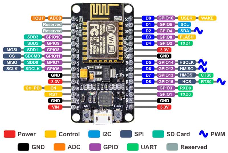
- NodeMCU - We will use this board as a micro-controller for this project.
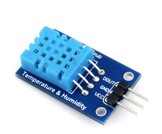
- DHT Sensor- From this sensor we can get values of temperature and humidity

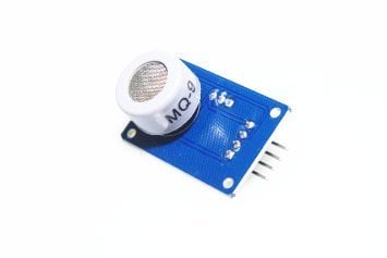
- MQ-9 Gas sensor- To sense the content of CO gas in the environment
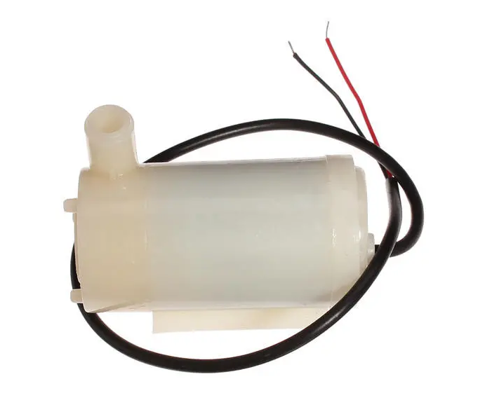
- Water Pump - Having same use as water pump
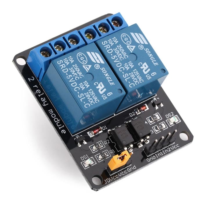
- 2 Channel relay board - Switch to trip high volt AC/DC applicances
- Exhaust fan - To control farm's temperature
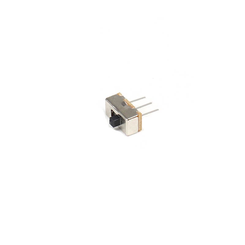
- Slide switch - Used to switch between two modes, self and manual.
- Jumper wires- For making connections
Step By Step Procedure
So this step will go into 3 major steps:
- App installation and Configuration
- Arduino code of blynk for irrigation
- Physical setup of project with circuit
1. App Installation and Configuration
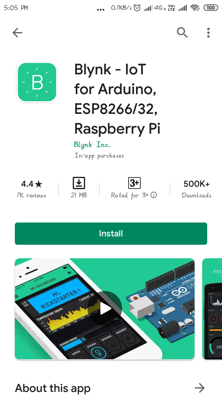
- Go to play store/app store and type blynk, you will find green color icon for blynk app, then install it on your device.
 Blynk App[/caption]
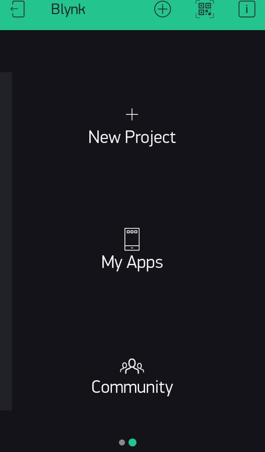
- Sign up with a gmail ID and then create a new project.
- then click on create option and fill the details like project name, device used and connection type.
 NewProject[/caption]
- As we are making Irrigation project, you can name it like smart Irrigation, just the way I did here,
- Auth token will be generated this auth token you will get in the settings option of this project and on your Gmail Account.
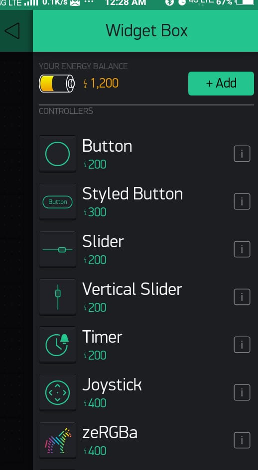
- Once your project is created, you have to insert different types of widget into it, For example I will be adding a button from widget box shown below.
 AddWidget[/caption]
[caption id="attachment_867679" align="aligncenter" width="395"]
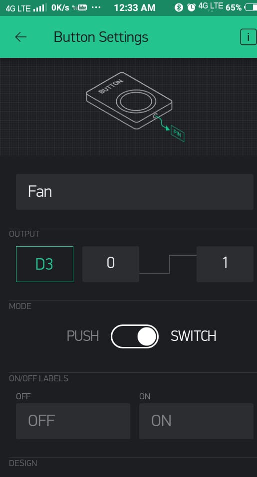 Fan[/caption]
- In the Above images I have taken button widget to turn On/Off my Exhaust Fan(In case you are using greenhouse farm)
[caption id="attachment_867680" align="aligncenter" width="371"]
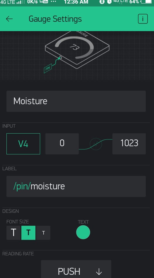 Moisture[/caption]
- I have also added a guage which will display moisture level of soil
[caption id="attachment_867681" align="aligncenter" width="368"]
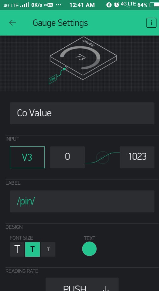 Co-Value[/caption]
- Covalue guage will display the pollution rate whose value will be taken from Co Sensor (MQ-9) sensor
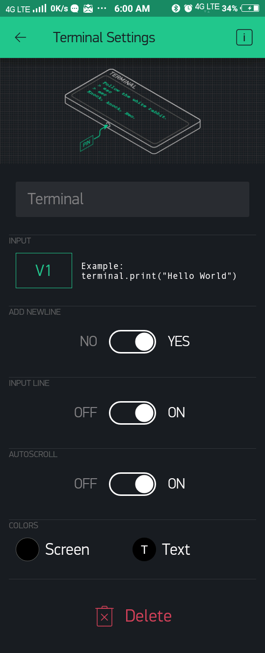 Terminal[/caption]
- Terminal widget is basically work as a serial terminal, whatever the data you want to print it on terminal, you can print it.
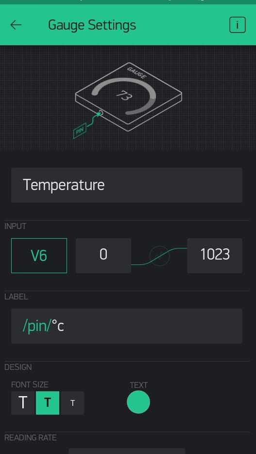 Temperature guage[/caption]
- This guage will print the value of current room temperatue of your farm, the value will be taken from DHT sensor
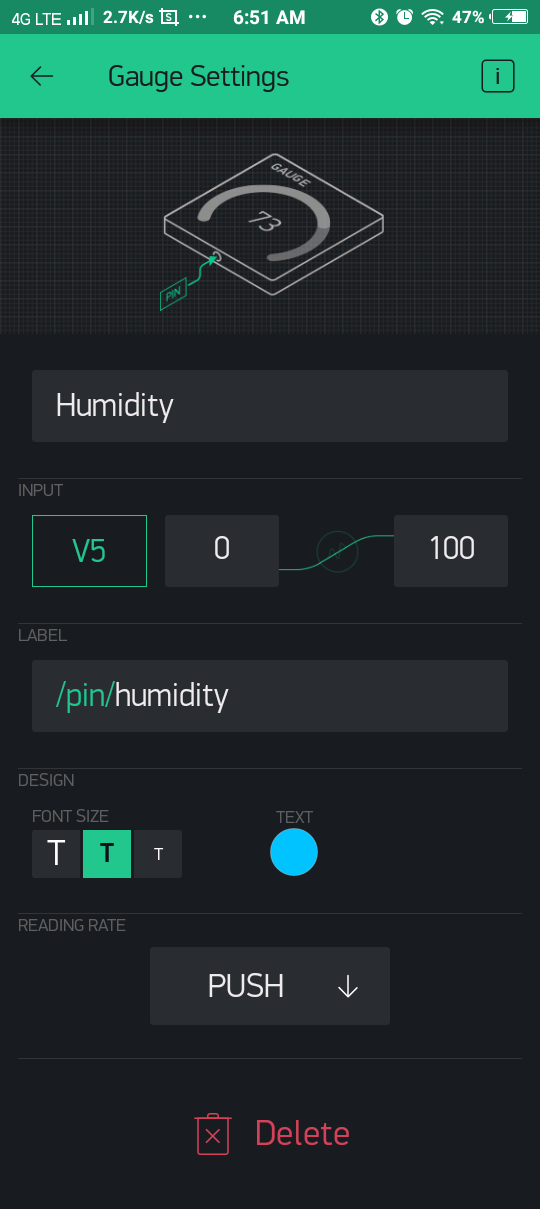 Humidity Guage[/caption]
- This will print the value of Humidity level whose value will be taken from DHT11 sensor.
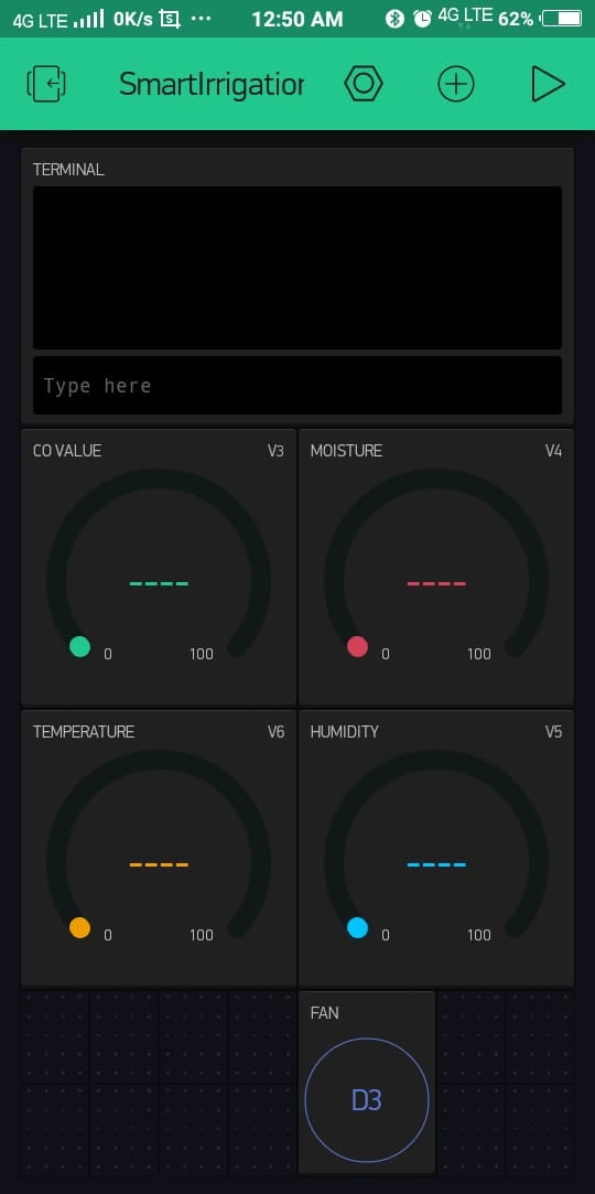 Dashboard[/caption]
[caption id="attachment_867690" align="aligncenter" width="367"]
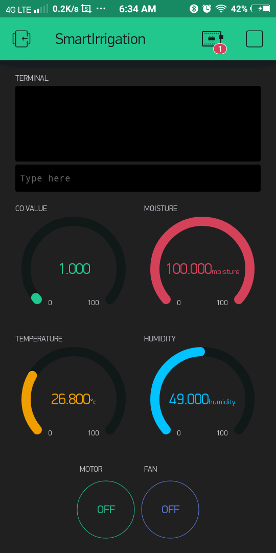 Dashboard[/caption]
- After adding all the necessary widget, the dashboard will look like this.
This is the complete step-by-step procedure of App installation and configuration.
2. Arduino Code and Setup
The next step will go to the code, if you're not much aware of the nodeMCU thing then don't worry, before proceeding with this section you can refer to the following link which tells you everything about the board and how to install it with Arduino
Hope you have read the above post now we directly jump to code,
- First of all, add all the libraries from the path Arduino library section
- For adding libraries follow the path in Arduino IDE itself, go to sketch/include library/manage library
- Enter the library used in this code,i.e. blynk, DHT,
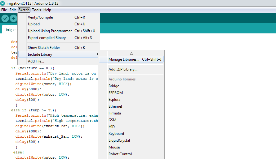 Manage library[/caption]
- DHT sensor library is for getting data from DHT sensor whereas we use blynk libary for running blynk operated tools.
[caption id="attachment_868430" align="aligncenter" width="544"]
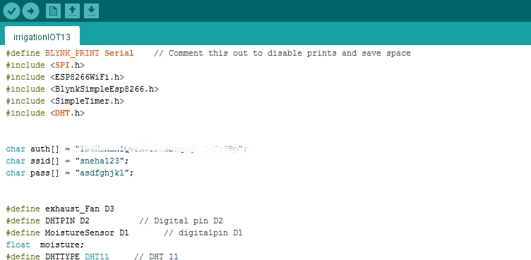 Adding All libraries[/caption]
- We have to add all the libraries like DHT.h, blynk libraries and ESP8266Wifi , for auth code you have to insert authentication code which was sent on your registered mail ID by blynk app, and for SSID and Password, you can insert your current WIFI network name and password
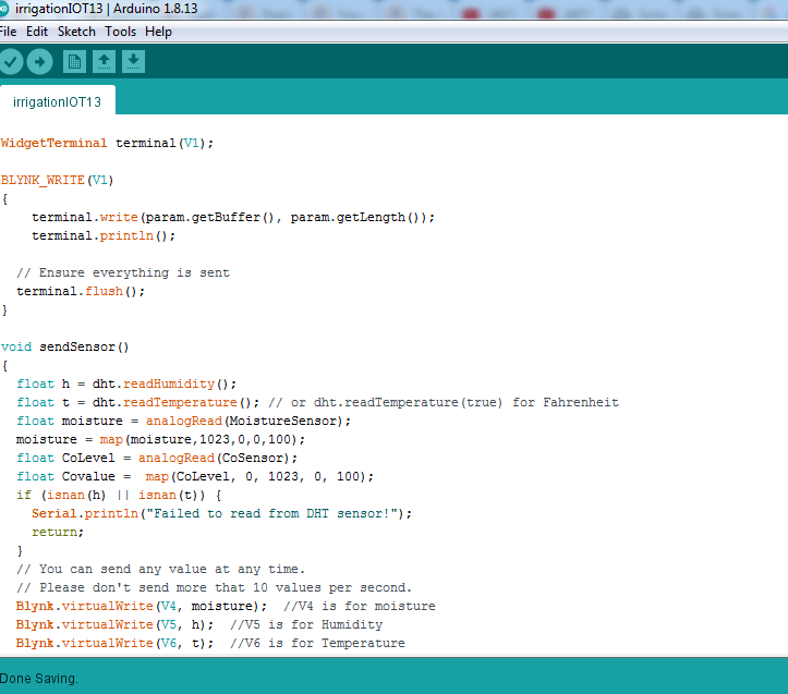 Adding Widget[/caption]
- The main purpose of adding Blynk library is for adding virtual widget to the code so that all the data can be virtually display on the dashboard of blynk, such as serial data, temperature, humidity, CoValue.
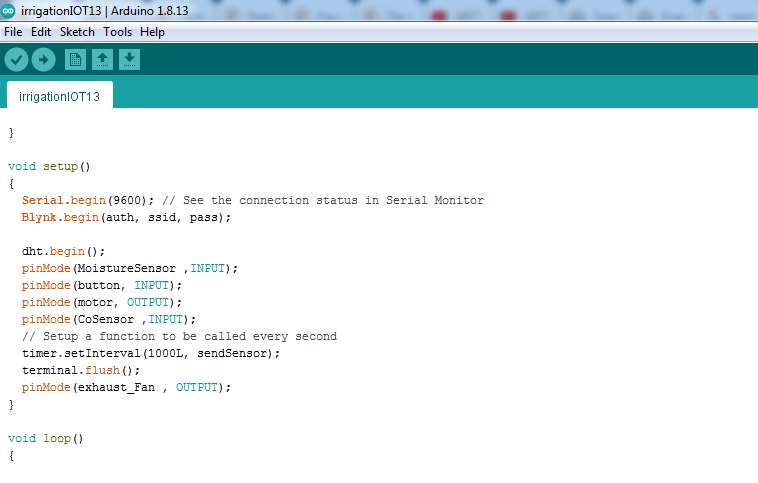 Void Setup[/caption]
- In the setup section we have added the line: Blynk.begin(auth, ssid, pass); is for initializing auth code your WIFI name and passoword of that wifi network.
Please find the link of complete code from the follwing link
Download Code
Flow of Code
Let me tell you the quick flow of code, means how this code will work,
- The code is get divided into 2 modes, automatic mode and manual mode.
- In manual mode we get all the value and we can control the appliances like fan or motor manually on our need/requirement
- While if we keep this project into Auto mode/ self Mode the system will work automatically depending upon current situation of your farm,
- For example if temperature goes beyond 40 degree celcius, it will turn on the fan, if the value of soil sensor is very low then it will turn on the water pump/motor.
- The manual mode and the Auto mode can be seperated by a SPDT switch, when we get logic 0 from button it will go to automatic mode otherwise it will be in manual mode.
3.Physical Setup of Project with Circuit
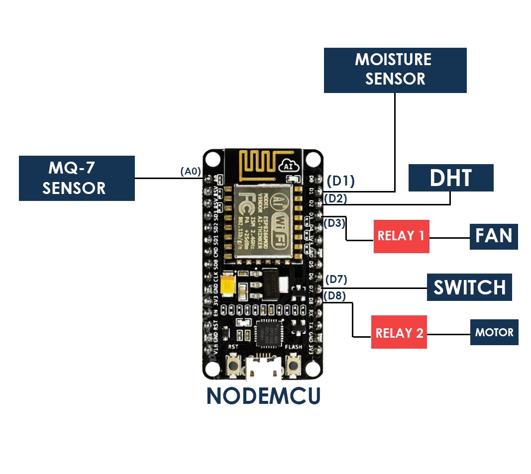
- Following image shows the block diagram of the code,
 Block Diagram_NODE[/caption]
- It is just a block digram to get a rough idea about how the which sensor are get connected its respective pins,
- It has included sensors and elements like DHT sensor, soil sensor , water pump, exhaust fan(if you doing greenhouse farm), CoSensor,and NodeMCU
- We have just make a prototype for this project but you can simply use this circuit for making your actual project.
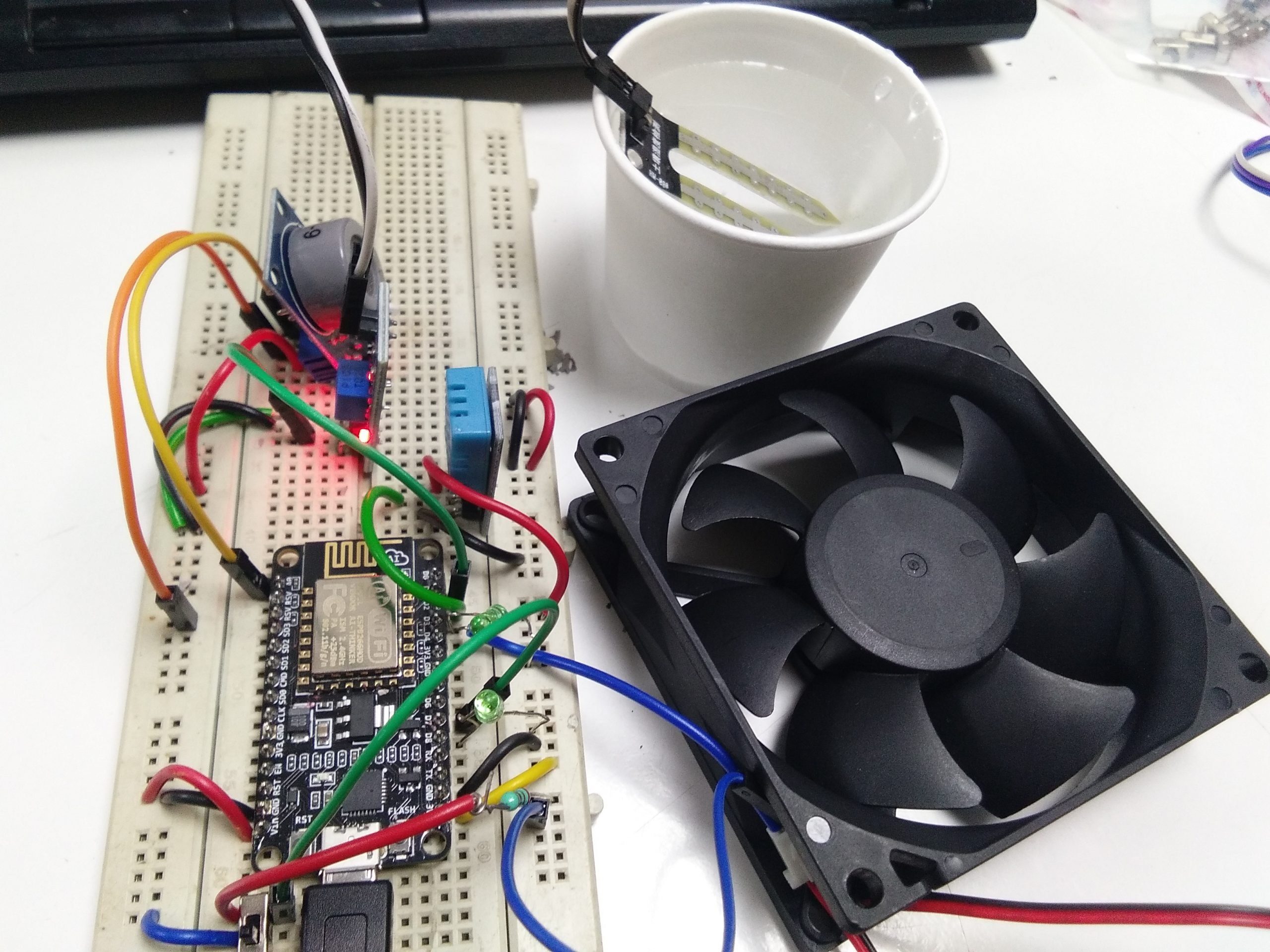 Setup Image[/caption]
Hope this little demonstration project will help you to build your IOT Based farm project.If you find any difficulties while building it, please drop your query in comment.





Good post. I learn something new and challenging on sites I stumbleupon everyday.
It will always be interesting to read content from other writers and practice a little something from their
web sites.