Introduction to STM32F407 Discovery Kit
STM provides extremely sophisticated and reasonable Microcontrollers. Discovery Boards with advanced features and simplicity helps the user to work efficiently on board.

Hello,
As an Embedded enthusiastic, If you are interested in twiddling with libraries and internal registers of microcontroller, the STM family is great to start with as they provide a wide range of ready to use libraries and IDEs. STM family have several microcontrollers boards, but fortunately, beginners functions are available in all. In this article, we are going to learn about the STM32F407 discovery board.
STM32F407 Discovery Board
It is the development board similar to Arduino, In addition to advanced features and accessibility. STM32F407 Discovery Board allows building high-reliability applications using an advanced performing microcontroller called Arm Cortex-M4 32-bit core. Here, I assume you must be familiar with ARM Architecture. It allows flexibility and customization so you can experiment with libraries, communication protocols, GPIO pins etc.
The feature list of the STM Discovery Board can be too long as per its capability. However, below I just mentioned a few of the features that may help you to understand it exactly.
Features:
- The core unit consists of Arm® Cortex®-M4 32-bit processor.
- Supports FPU and DSP instructions for high speed.
- Have 100-pin LQFP package.
- Uses ST-LINK/V2 embedded debug tool for programming and debugging.
- Built-in 3-axis accelerometer and Omni-directional digital microphone.
- Built-in audio DAC along with class D type speaker driver.
- Consist of a total of 8 LEDs, of which 4 are User LEDs.
- Consist of user and reset push-buttons.
- Support wide range of IDEs
- Flexible power supply options.
- Core operates at a frequency of 168MHz
- Seven channel matrix AHB bus for fast switching.
- Support I2C. SPI, as well as UART modes for communication.
- Low power operation.
Hardware:
As the below image depicted, the board consist of Power LED, Audio jack, Micro USB port, SWD (Serial Wire Debug), Mini USB ST-Link debugger, User and Reset buttons, Header pins, Crystal oscillator and four user LEDs (Red, Orange, Blue and Green) etc. The board consists of headers pins connected to the Five ports of the core, i.e. A, B, C, D and E.

Firstly establish a connection between board and computer using a USB type A to Mini B Cable. This cable is connected through a USB connector CN1 on the board. The four user LEDs starts blinking in one by one manner. STM32 DISC board have preloaded program for MEMS sensor. As you press the user button on the board, the sensor will enable.When you tilt or move the board, the LEDs represents the direction and speed of movement.
User manual and Datasheet are extremely important while working on the board because the information about GPIO pins, Layout and various configurations of MCU are thoroughly described in it.
Softwares:
STM32 Discovery Board is compatible with several IDEs so that you can choose according to your convenience. Here I have mentioned the list of IDEs that are compatible with the STM Boards.
I have used an Atolic Truestudio for programming the board, as it is easy to install libraries and simple to use. Make sure to install STM32 ST-LINK Utility on your device before uploading the code. Procedure and guidelines for creating a project, uploading code, and debugging vary as per the IDE.
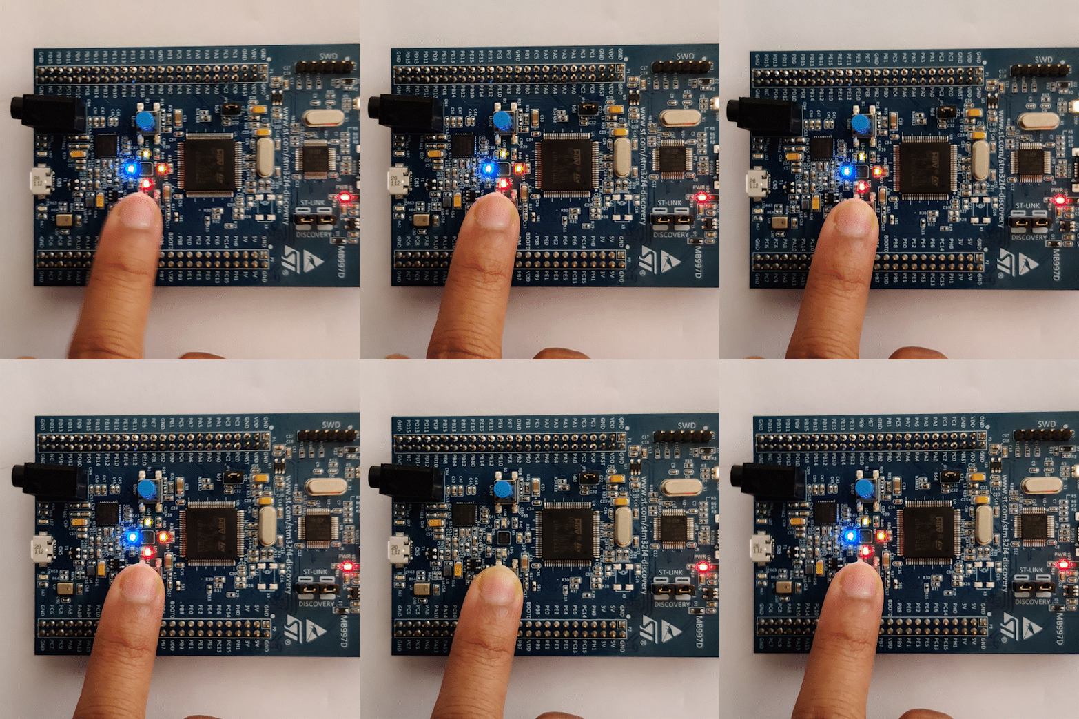
As you can see above GIF, I have uploaded a basic interrupt program in a Board. All four LEDs remains ON until the interrupt is introduced. This interrupt can be introduced using the Reset button on the board.
Final Thoughts:
I hope now you are familiar with the STM32F07 Discovery Board. Learning and working on STM boards requires Patience, Interest and Consistency. If you have any thoughts regarding it, please let us know in the comment section.


