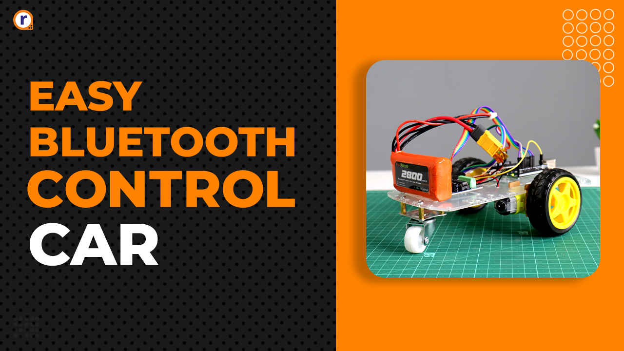
How To Make A Line Follower And A Bluetooth Controlled Robot
This blog will cover designing a line follower and a Bluetooth controlled robot using various sensors and Arduino.

Robots are becoming more demanding day by day. In today's automation world everyone is busy designing robots to reduce the cost of production and the damage caused by human errors. Line following and Bluetooth controlled bots are also part of the era of automation. So, in this blog, we are designing a line follower and a Bluetooth controlled robot. And after completing this blog you will understand the basics of motor driver, HC-05 and line sensor.
What is Line follower Robot?
Baisically, it is a robot designed to follow the line and automatically deliver the object to its destination. This robot uses a closed-loop system to follow the track accurately.
If you check the above image, you will see two to three LED kind of things at the bottom of the robot. These LEDs are nothing but an IR sensor. If you want to know the working of IR sensor, then I request you to check this blog of mine. In that blog, I have explained everything you want to know about IR sensors.
Coming to the point, these IR sensors are mounted on the lower part of the robot which tracks the line and moves towards its destination according to the received input.
What Is HC-05 Bluetooth Controlled Robot?
This type of robot uses the HC-05 Bluettoh Module . This module receives input from the smartphone and functions according to commands received from the user.
I have already written a blog on HC-05 in which I have explained everything about interfacing of HC-05 with Arduino. If you want to know about HC-05 in details, then I request you to check out this HC-05 blog.
It was about the basic introduction of all these subjects, now what do you think are the other components that you might need in the design of a robot? No information !! Don't worry, I tell you.
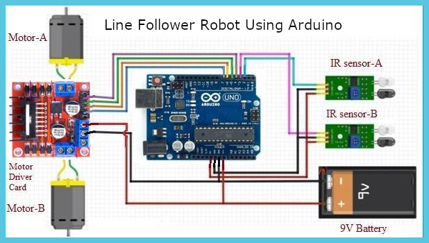
Circuit Diagram For Line Follower Robot

Till this point what we have discussed up to this point was about the basic introduction of line follower robots and Bluetooth controlled robots, now what do you think are the other components that you might need in the design of a robot? No idea !! Don't worry, I’ll tell you.
Components You May Require to Design A line Follower Robot and a Bluetooth controlled robot
Chassis For The Robot
When building a robot, the first thing you should keep in mind is the chassis. The chassis is like a robot's skeleton that gives strength to the robot.
The chassis is like the backbone of any robot and therefore care must be taken when designing but thanks to Robu, they have already designed the chassis for people like us and this is a product link.
Wheels and the Motors
These are two things that you should select wisely because the load carrying capacity of the robot depends on these two things. So, these things must be selected wisely. And if you want to know more about the selection of Motors then please check this blog. It will clear all your doubts related to the selection process of the wheels and Motors.
Line Sensor
Line sensors are nothing but an active IR sensor. It consists of a transmitter and a receiver. The transmitter is nothing but an IR source, which emits IR rays continuously and when these rays collide with an object, these rays return from there to the module. An IR detector mounted on the sensor captures those reflected rays and these signals are then delivered to the microcontroller which detects the presence of the object based on the instruction the programmer has stored in the program memory.
For the line follower sensor, we are using black tape and we have patched it onto the reflective surface. When the IR light falls on the black tape, the IR rays will be absorbed from the surface and if those rays fall on the reflective surface then it will reflect back to the sensor and in this way, by calculating the reflected signals we will decide whether the robot is on the track or not.
L298N Motor Driver
This is one of the important things on a robot that you need to choose carefully. With the help of the motor, you can change the direction of the motor also you can increase or decrease the speed of the motor. The motor-driver consists of an H-bridge drive or if I say in simple terms it is a four-quadrant DC to DC converter which is responsible for driving the motor. In this project, we are using L298N motor-driver.
But why are we using motor-driver here? Why we connect the DC motor directly to the Arduino?
The Answer to this question is no, we cannot power the DC motor through the Arduino and the reason is, the DC motor requires 2 amperes of current but the Arduino only generates about 50Amp current on its GPIO pin, so if we power the motor through the Arduino, the Arduino will burn.
HC-05 Module For Bluetooth Controlled Car
As you know the HC-05 supports Bluetooth technology, it can be easily paired with your smartphone and can be used to control robots easily. This is why we have used HC-05 in our project. I have already written a blog on HC-05 Bluetooth module, if you want to know more about Bluetooth module then you can check this link.
Code For Line Follower Robot
Before we start writing code for Arduino, we need to design an algorithm first so that whatever code we write using this algorithm can run smoothly.
So what do you think the algorithm should be like? Don't know let's discuss. We got two IR line sensors for this project and that we are going to mount on the chassis as shown in the picture below. After mounting the sensor on the chassis, place the bot on the track in such a way that the black tape falls exactly between the two sensors.
When we will power these sensors, these sensors will generate a high-level output or a LOW-level output. (If the sensor is on tape it will generate a LOW-level signal and if the sensor is on the reflective surface it will generate a high-level signal)
Having done this the next thing is we will have to design a decision-making system for our robot.The following situations can help you to make a set of decisions.
-
First Situation
If the bot side sensors are low, it means that the bot is running correctly and to keep it running we have to use the following line of code.
If (LineSensor2 == LOW && LineSensor1 == LOW )

{

  DigitalWrite(Left_motor1, HIGH)

  DigitalWrite(Left_motor2, LOW)

  DigitalWrite(Right_motor1, HIGH)

  DigitalWrite(Right_motor2, LOW)

} -
Second Situation
If the right-sensor is LOW and the second sensor is HIGH, it means that the robot is moving to the left-direction and to return it to its original position we have to use the following line of code.
If (LineSensor1 == LOW  && LineSensor2 == HIGH)

{

  DigitalWrite(Left_motor1, HIGH)

  DigitalWrite(Left_motor2, LOW)

  DigitalWrite(Right_motor1, LOW)

  DigitalWrite(Right_motor2, LOW)

} -
Third Situation
If the robot is rotating in the left direction, that position will make the left sensor high and the right sensor low. In that case, we have to turn off the left motors to return the robot to its original position. And to do this we have to use the following method.
 If (LineSensor1 == HIGH  && LineSensor2 == LOW)

{

  DigitalWrite(Left_motor1, HIGH)

  DigitalWrite(Left_motor2, LOW)

  DigitalWrite(Right_motor1, LOW)

  DigitalWrite(Right_motor2, LOW)

} -
Forth Situation
What will you do if our robot unfortunately loses its way? The answer to this question is very simple, if the robot has lost its way, all the sensors will generate a low-level signal or a high level. So in such case, we have to stop our robot and we can use the following method to do so.
If ((LineSensor1 == HIGH  && LineSensor2 == HIGH ) || (LineSensor1 == LOW  && LineSensor2 == LOW))

{

  DigitalWrite(Left_motor1, LOW)

  DigitalWrite(Left_motor2, LOW)

  DigitalWrite(Right_motor1, LOW)

  DigitalWrite(Right_motor2, LOW)

}
In this way we have created a decision-making system for line follower robot, this decision system will help our robot find its way. The full code for the line follower robot is as follows.
int LineSensor1 =  2;
int LineSensor2 =  3;
int leftMotor1  =  4;
int leftMotor2  =  5;
int rightMotor1 =  6;
int rightMotor2 =  7;

int leftValue =  0;
int rightValue = 0;
void setup()
{
  pinMode (leftMotor, OUTPUT);
  pinMode (rightMotor, OUTPUT);
  pinMode (LineSensor1, INPUT);
  pinMode (LineSensor2, INPUT);

}
void loop()
{
  leftValue = digitalRead (leftInput);
  rightValue= digitalRead (rightInput);

if (LineSensor2 == LOW && LineSensor1 == LOW )

{

  DigitalWrite(Left_motor1, HIGH)

  DigitalWrite(Left_motor2, LOW)

  DigitalWrite(Right_motor1, HIGH)

  DigitalWrite(Right_motor2, LOW)

}
else if (LineSensor1 == LOW  && LineSensor2 == HIGH)

{

  DigitalWrite(Left_motor1, HIGH)

  DigitalWrite(Left_motor2, LOW)

  DigitalWrite(Right_motor1, LOW)

  DigitalWrite(Right_motor2, LOW)

}
 else if (LineSensor1 == HIGH  && LineSensor2 == LOW)

{

  DigitalWrite(Left_motor1, HIGH)

  DigitalWrite(Left_motor2, LOW)

  DigitalWrite(Right_motor1, LOW)

  DigitalWrite(Right_motor2, LOW)

}
  eles if ((LineSensor1 == HIGH  && LineSensor2 == HIGH ) || (LineSensor1 == LOW  && LineSensor2 == LOW))

{

  DigitalWrite(Left_motor1, LOW)

  DigitalWrite(Left_motor2, LOW)

  DigitalWrite(Right_motor1, LOW)

  DigitalWrite(Right_motor2, LOW)

}
Circuit Diagram for Bluetooth controlled Robot
Code For Bluetooth Controlled Robot
Up to this point, we have talked about how to design code for a line follower robot, in this part of this blog we are designing a code used to control a robot using your smartphone goes. To do this, you need to pair the smartphone with HC-05.
Once you successfully connect the Bluetooth module to the smartphone, you will need to install this app in your phone and using the following code you are ready to control your robot manually.
In this code, we have used the softwareserial.h library to establish communication between the Arduino and HC-05 Bluetooth modules. And using this app we are sending commands to the Arduino.
#include<SoftwareSerial.h>

#define IN1 4
#define IN2 5
#define IN3 6
#define IN4 7
#define EN1 9
#define EN2 10

SoftwareSerial mySerial(2, 3); // RX, TX

String data;
int btVal;

void setup()
{
  //Serial.begin(115200);
  pinMode(IN1, OUTPUT);
  pinMode(IN2, OUTPUT);
  pinMode(IN3, OUTPUT);
  pinMode(IN4, OUTPUT);
  pinMode(EN1, OUTPUT);
  pinMode(EN2, OUTPUT);
  digitalWrite(IN1, LOW);
  digitalWrite(IN2, LOW);
  digitalWrite(IN3, LOW);
  digitalWrite(IN4, LOW);
  digitalWrite(EN1,HIGH);
  digitalWrite(EN2,HIGH);
  mySerial.begin(9600);
}

void loop()
{
 while (mySerial.available())
 {
  {
      data = mySerial.readStringUntil('\n');
      Serial.print(str);
  }

     btVal= (data.toInt());
    Serial.print("BlueTooth Value ");
    Serial.println(btVal);


  switch (btVal)
   {
      case 1:
        Serial.println("Forward");
        forward();
        break;

      case 2:
        Serial.println("Reverse");
        reverse();
        break;

      case 3:
        Serial.println("Left");
        left();
        break;

      case 4:
        Serial.println("Right");
        right();
        break;

      case 5:
        Serial.println("Stop");
        stoprobot();
        break;

  }

 }


   if (mySerial.available() < 0)
    {
     //Serial.println("No Bluetooth Data ");
    }

}

void forward()
{
  digitalWrite(IN1, HIGH);
  digitalWrite(IN2, LOW);
  digitalWrite(IN3, HIGH);
  digitalWrite(IN4, LOW);
}

void reverse()
{
  digitalWrite(IN1, LOW);
  digitalWrite(IN2, HIGH);
  digitalWrite(IN3, LOW);
  digitalWrite(IN4, HIGH);
}

void left()
{
  digitalWrite(IN1, LOW);
  digitalWrite(IN2, LOW);
  digitalWrite(IN3, HIGH);
  digitalWrite(IN4, LOW);
}

void right()
{
  digitalWrite(IN1, HIGH);
  digitalWrite(IN2, LOW);
  digitalWrite(IN3, LOW);
  digitalWrite(IN4, LOW);
}

void stoprobot()
{
  digitalWrite(IN1, LOW);
  digitalWrite(IN2, LOW);
  digitalWrite(IN3, LOW);
  digitalWrite(IN4, LOW);
}
Conclusion-
In this blog, we have learned how to design a line following and a bluetooth controlled robot, i hope you liked this content. If there are any doubts please let us know in the comment section and we will definitely snswer them.


