This blog will cover the interfacing of HC-05 bluetooth module with Arduino board.

In this blog, we will discuss the interfacing of HC-05 with Arduino board. After reading this blog you will understand what HC-05 module is, how it can be used in the IoT area, HC-05's interface with Arduino Uno, and some other interesting things.
In our previous post, we talked about interfacing the Sim800L with the Arduino and we talked about the SIM800L AT command.
But hold on why I'm referring you to my previous blog? Because in our previous blog we talked about GSM module which uses IEEE 802.11 and Bluetooth uses IEEE 802.21. But what does this mean? What is the IEEE standard? IEEE stands for "Institute of Electrical and Electronics Engineers".
Under the awning of the IEEE, a group of "pro persons" comes together and defines certain rules and guidelines for the term electronics and computers. These standards are used by developers to design their products.
Both GSM and HC-05 can be used in IoT applications, but assume that you are building a digital application where multiple nodes are sharing data and are kept at a short distance for communication purposes and if you use the GSM module for this application, the cost of the product increases and it also affects the complexity of the project, the remedy on this issue is the use of the short-distance communication modules such HC-05, ZIGBEE.
If you are acquiring data from the small plant then using Bluetooth is the most effective way but if you are acquiring data from a city or large plant where the nodes are placed far away from each other then using GSM-like modules would be suitable to use.
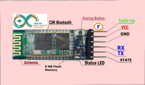
 HC-05 Pinout[/caption]
The HC-05 Bluetooth module uses UART communication to transfer data to the master and uses two pins Rx and Tx to do this job. The pinout details of the HC-05 device are as follows:
 Ok, I hope you have made the connection, now we need to write code for HC-05 to enable communication between Arduino and HC-05, but we know that HC-05 uses UART, means that we have to write UART code or we can use the built-in libraries to simplify it.
For this section, we are using the built-in library, as I do not want to overload this tutorial with coding stuff, but if you want me to make a tutorial on serial communication for Arduino let me know in the comments section. I will try to clear all your doubts related to UART in Arduino in our new blog.
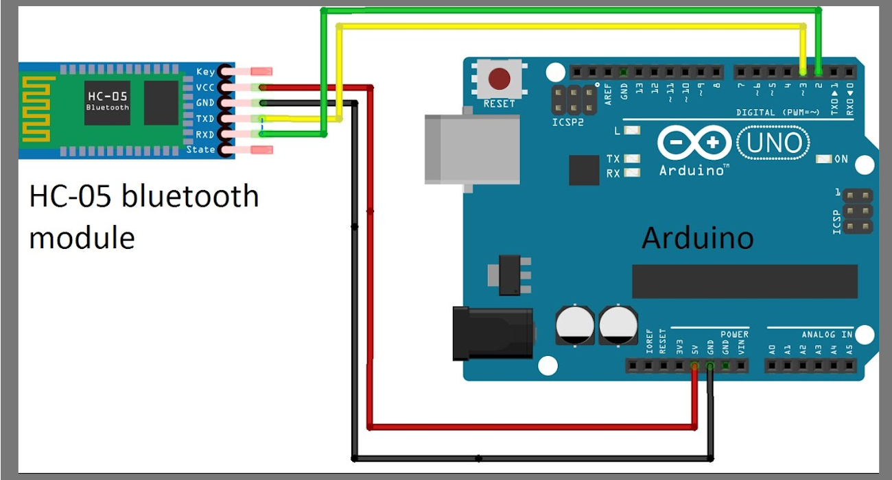
In the above code, we have used the built-in library for serial communication and using this code we are reading the 'char' which is received from the smartphone. For serial communication, we have assigned PIN 2 and PIN 3 of Arduino for serial communication.
After powering the setup, the HC-05 connected on the Arduino board will receive the data from the smartphone and this data will be collected serially by the character “data” and based on the IF ELSE condition the Arduino will execute the operation.
Up to this point we had talked about the code for Arduino, using this code we would be able to get commands from the smartphone, but even though the smartphone is connected to HC-05, it is not able to send commands because the software that will control the Bluetooth is not yet installed on the smartphone. So, first, we have to install the software to enable the smartphone to transmit data.
You can use our own HC-05 android software which is available on Google Play Store. I have shared the link google play store link below please take a look.
Google Play Store link for HC-05 android app
 In this blog, we have talked about the functionality of the HC-05 Bluetooth module and also learned about its interfacing with Arduino Uno and 8051.
I hope this blog helps in your project. If there is any doubt, please let me know in the comment section.
HC-05 Module -
The HC-05 offers many more features such as low power data transmission, high-speed data transfer and many more. It is a full-duplex communication which means both sender and receiver transmit and receive data at a time. Besides, the HC-05 FHSS uses frequency-hopping spread spectrum radio technology. This technique provides many advantages of communication over a noisy channel and prevents the signal from being hacked or jammed. By this point, we were talking on the HC-05's features and we showed how it is an alternative option for short-distance communication. Later we are going to talk about its pinout diagram and its interfacing with Arduino Uno, 8051.Pinout of HC-05
[caption id="attachment_668458" align="aligncenter" width="716"] HC-05 Pinout[/caption]
The HC-05 Bluetooth module uses UART communication to transfer data to the master and uses two pins Rx and Tx to do this job. The pinout details of the HC-05 device are as follows:
1 VCC and GND
These pins are used to power the module2 Rx and Tx
These pins are used for communication purpose3 State
This pin tells us whether the module is paired or not4 EN
This pin is an active low pin and it defines the mode of operation of HC-05.HC-05 has two modes of operation those are as follows:
1. Data Mode
By default, HC-05 mode works in data mode. In this mode, HC-05 sends and receives data from other devices.2. Command Mode
In this mode, HC-05 accepts AT commands from the user and reacts to the commands accordingly.Interfacing HC-05 with Arduino Uno:
In this section, we are going to learn how to interface Arduino Uno with HC-05. To complete this project you will need the following components. Hardware parts SoftwaresHC-05 Interfacing Diagram
If you're full of all these things in your backup, let's move on to our next destination, which is the HC-05's interface with the Arduino. For interfacing diagram, you can refer the below image Ok, I hope you have made the connection, now we need to write code for HC-05 to enable communication between Arduino and HC-05, but we know that HC-05 uses UART, means that we have to write UART code or we can use the built-in libraries to simplify it.
For this section, we are using the built-in library, as I do not want to overload this tutorial with coding stuff, but if you want me to make a tutorial on serial communication for Arduino let me know in the comments section. I will try to clear all your doubts related to UART in Arduino in our new blog.
Code for HC-05
"" HC-05 With Arduino ""
#include <SoftwareSerial.h>
SoftwareSerial BTSerial(2, 3); // RX, TX
void setup()
{
// Open serial communications and wait for port to open:
Serial.begin(9600);
while (!Serial) {
; // wait for serial port to connect. Needed for Native USB only
}
// set the data rate for the SoftwareSerial port
BTSerial.begin(9600);
BTSerial.println("Hello, world?");
}
char BTSignal;
void loop() // run over and over
{
//Serial.println(" Blutooth is connected ");
while (BTSerial.available())
{
BTSignal = Serial.write(BTSerial.read());
Serial.write(BTSignal);
Serial.println(" ");
break;
}
}
Android software for HC-05
Install the above application and follow all the instructions. Once you have done all this, connect both modules. I have seen many module manufacturers providing onboard pairing mode button. If you have this type of module then press this button while pairing the module with the smartphone and if it asks for the password you can enter '0000' or '1234' and that's it your Arduino is now ready to get controlled by your smartphone. Here's a look at how this sensor works in real time with Arduino.Interfacing HC-05 with 8051
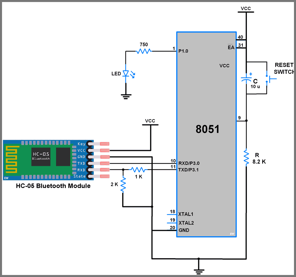
Up to this point we have talked about the interfacing of HC-05 with Arduino Uno. In this section, we are talking about the interfacing of HC-05 with 8051 microcontrollers. For this tutorial, we are using pin 10 and pin 11 of 8051 to interface HC-05 and talking about code and interfacing the diagram, I have shared all the things below.Sample code for HC-05
/* HC-05 with 8051 */
#include <reg51.h>
#include "UART_H_file.h"/* Include UART library */
sbit LED=P1^0;
void main(){
char Data_in;UART_Init();/* Initialize UART */
P1 = 0;/* Clear port initially */
LED = 0;/* Initially LED turn OFF */
while(1){
Data_in = UART_RxChar(); /* Receive char serially */
if(Data_in == '1'){
LED = 1;/* Turn ON LED */
UART_SendString("LED_ON"); /* Send status of LED*/
}
else if(Data_in == '2')
{LED = 0;/* Turn OFF LED */
UART_SendString("LED_OFF"); /* Send status of LED*/
}
elseUART_SendString("Select proper option");
}
}
Interfacing Diagram For 8051
 In this blog, we have talked about the functionality of the HC-05 Bluetooth module and also learned about its interfacing with Arduino Uno and 8051.
I hope this blog helps in your project. If there is any doubt, please let me know in the comment section.


liked the flow of the blog.
Thank you for taking out the time to read out our blog and sharing your valuable feedback.