Servo Motor & Raspberry Pi Pico Can Build servo control system! Here You See How You build your own?
In This Blog ,We Will See How a Servo Motor and Raspberry Pi Pico Used to Make a Project Which Helps Out to Make Own Servo Control System .A servo
In This Blog ,We Will See How a Servo Motor and Raspberry Pi Pico Used to Make a Project Which Helps Out to Make Own Servo Control System .A servo motor is used in applications where precise steering and position control is required. A servo motor has rotary encoder feedback which enables it to lock at a specific angle. It has inbuilt gearbox which increases the torque of the motor.
Applications Of Servo Motor
- Robotic arms - Servos are a basic part of the robotic arm. It is used to control the angle of the arm.
- Camera - Servos are used to do the auto-focusing.
- Metal machinery – CNC and cutting machines are one of the main uses of servo motors.
- Remote control applications – To actuate or rotate a mechanical part in a model car, or airplane using a remote.
There are many types of servo motors. It depends on the application of the user. Industrial servo motors have more precise encoders and high torque capability. For DIY projects, hobby servo motors are used.
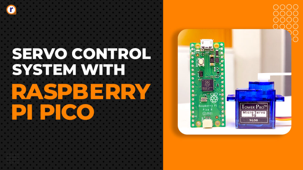
Here we are using an SG90 servo motor. The SG90 is the best hobby servo motor, to begin with. Its torque is 2.5kg/cm and its speed is 0.1 sec/60 degrees. The operating voltage is 5V.
To control the angular position of the shaft we have to give a proper control signal to the orange wire. The control signal is a PWM signal. Gather the components given in the list.
Components list
- Raspberry pi pico
- USB cable
- SG90 servo motor
- Jumper wires (M to F) – 3ps
Connect the servo motor according to below-given circuit diagram -

The servo motor operates on 5 volts. The servo motor gets 5V from Raspberry pi pico. The VBus pin on Raspberry Pi pico outputs 5V. The red wire is connected to the VBus pin and the brown wire is connected to the 3rd pin which is ground. The orange wire is the wire which carries the PWM signal and it’s given to PWM pin 15 of Raspberry Pi pico. All GPIO pins on Raspberry pi pico support PWM. The servo motor can be connected to any pin.
PWM Signal For Servo Motor
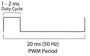
According to the datasheet. The PWM signal is as follows: -
The PWM period is 20ms. Frequency is 1/Time period, therefore 1/20ms is 50Hz. We need to generate a PWM signal of 50Hz.
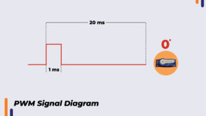
When the on-time is 1ms the shaft angle is at 0 degrees.
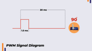
When on-time is 1.5ms the shaft angle is at 90 degrees.
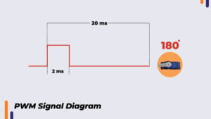
When on-time is 2ms the shaft angle is at 180 degrees.
For 20ms on time the number to be passed in the function “pwm. duty_u16()” is 65535. If we want an on-time of 1ms, here is calculation -
(65535*1ms)/20ms = 3276.75 which approximates to 3277
Therefore, the number we are going to pass in function is 3277.
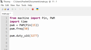
Below given is the code to generate a PWM signal of on-time 1ms and frequency 50Hz using raspberry pi pico.
This code, although it’s generating on-time of 1ms. The shaft angle is not 0 degree. To get to a proper number corresponding to 0 degree. We must go on lowering the number and upload the code until we reach 0 degrees angle. At 0 degrees the number is 1800. In a similar way, I found out for 180 degrees. The number is 8000 for 180 degrees.
In the range of 1800 to 8000 we get angular rotation from 0 degrees to 180 degrees. This means there are 8000 – 1800 = 6200. 6200 divisions between 0 to 180 degrees. Then for 1 degree, the number is 6200/180= 34.45. This number is the constant that we can use to create a function to move the servo as per angle input.
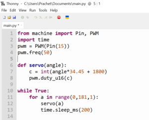
Program with function -
The function accepts the angle. The angle is multiplied by 34.45 and that number is added to 1800. As 1800 corresponds to 0 degree. That gives us proper number corresponding to the angle passed in the function. The angle number is stored in a variable “c” and that variable is passed in the “PWM.duty_u16()” function which rotates the servo shaft to the desired angle.
Conclusion
In this way, we can pass any angle in the range of 0 to 180 degrees in our function and move the servo to desired angle using raspberry pi pico. If you have any doubt regarding any part of this blog then feel free to comment on it. Our team will be there to assist you.
For more electronics projects. Check out our YouTube channel


