A Beginner Guide to NodeMCU
The blog will guide you through the getting started process for the NodeMCU.
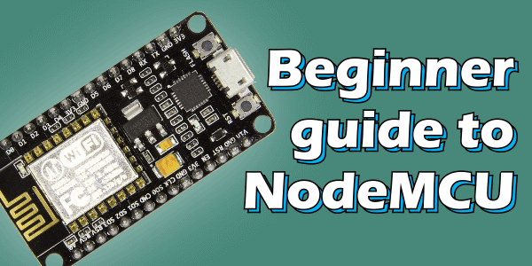
If you’re familiar with Arduino, using NodeMCU is a logical next step if you’re looking for a more compact, WiFi-equipped alternative. NodeMCU is based on the Esperessif ESP8266-12E WiFi System-On-Chip. It is loaded with an open-source, Lua-based firmware. To getting started with NodeMCU is very easy, lets stay connect with us.
It’s perfect for IoT Applications, and other wireless connectivity applications. This chip has a great deal in common with the Arduino – they’re both microcontroller-equipped prototyping boards which can be programmed using the Arduino IDE. The ESP8266 is a more recent released than the Arduino, it also has stronger specifcations. It has a 32-bit RISC processor clocked at 80MHz, along with a generous RAM complement and support for up to 16 MB of external flash storage.
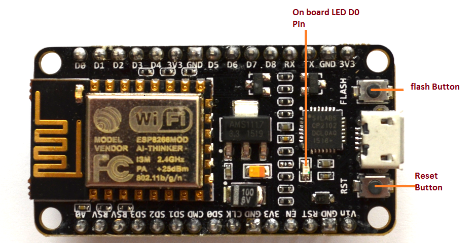
[caption id="attachment_748140" align="aligncenter" width="485"]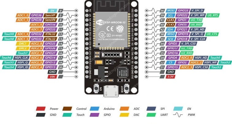 nodemcuPinout[/caption]
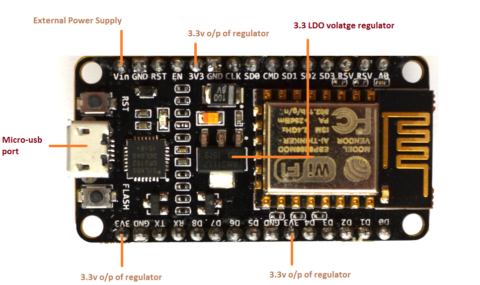
The device is especially useful for IoT applications, thanks to its tiny footprint and built-in WiFi support. The ESP8266 Integrates 802.11b/g/n HT40 Wi-Fi transceiver, so it cannot only connect with a WiFi network and interact with the Internet. It can also set up a network of its own, allowing other devices to connect directly to it. There’s an on-board voltage regulator that ensures the cleanest possible power to the MCU itself, as well as a push-button reset and a USB connection for easy interface with your computer. In this blog, we are going to see getting started with nodemcu in detail, So we start with its power requirements. Operating voltage range of ESP8266 is 3 to 3.3v. The NodeMCU board has inbuilt LDO voltage regulator which keep the voltage level at 3.3v. In case of current it supply 600mA reliably.
Power Requirements:
- Operating voltage : 2.5 to 3.3 v
- Onboard 3.3v 600mA voltage regulation
- 800mA operating current
- 20 µA during sleep mode
- You can provide voltage upto 16.6v
[caption id="attachment_747990" align="aligncenter" width="487"]
 power pins-Nodemcu[/caption]
On Board Switches and LED Indicator:
ESP8266 comes up with 2 switches one is reset and another one is flash button, Reset button is use offcourse to reset nodemcu and flash button is used to download and is used while upgrading the firmware. The board also has build in LED indicator which is connected to D0 pin and can be programable.
Serial Communication:
The Nodemcu includes CP2102 USB-to-UART Bridge Controller, helps to converts USB signal to serial and allows your computer to program and communicate with the ESP8266 chip. It also has 4.5Mbps communication speed.
I/O Pins and Peripherals:
The ESP6266 Nodemcu board comes up with 17 GPIO ,this pins assign to all types of peripheral duties like
- A 10 bit ADC channel
- PWM output
- UART interface
- SPI, I2C, I2S interface : to connect all sort of sensors and devices
- I2S: to add sound to your project.
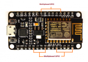
Thanks to the ESP8266’s pin multiplexing feature (Multiple peripherals multiplexed on a single GPIO pin). i.e a single GPIO pin can act as a PWM/UART/SPI.
ESP8266 NodeMCU Pinout:
Power Pins
There are four power pins viz. one VIN pin & three 3.3V pins. The VIN pin can be used to directly supply the ESP8266 and its peripherals, if you have a regulated 5V voltage source. The 3.3V pins are the output of an on-board voltage regulator. These pins can be used to supply power to external components.
Ground
It is a ground pin of ESP8266 NodeMCU development board.
I2C pins
These pins are used to hook up all sorts of I2C sensors and peripherals in your project. Both I2C Master and I2C Slave are supported. I2C interface functionality can be realized programmatically, and the clock frequency is 100 kHz at a maximum. It should be noted that I2C clock frequency should be higher than the slowest clock frequency of the slave device.
GPIO Pins
ESP8266 NodeMCU has 17 GPIO pins which can be assigned to various functions such as I2C, I2S, UART, PWM, IR Remote Control, LED Light and Button programmatically. Each digital enabled GPIO can be configured to internal pull-up or pull-down, or set to high impedance. When configured as an input, it can also be set to edge-trigger or level-trigger to generate CPU interrupts.
ADC Channel
The NodeMCU is embedded with a 10-bit precision SAR ADC. The two functions can be implemented using ADC viz. Testing power supply voltage of VDD3P3 pin and testing input voltage of TOUT pin. However, they cannot be implemented at the same time.
UART Pins
ESP8266 NodeMCU has 2 UART interfaces, i.e. UART0 and UART1, which provide asynchronous communication (RS232 and RS485), and can communicate at up to 4.5 Mbps. UART0 (TXD0, RXD0, RST0 & CTS0 pins) can be used for communication. It supports fluid control. However, UART1 (TXD1 pin) features only data transmit signal so, it is usually used for printing log.
SPI Pins
ESP8266 features two SPIs (SPI and HSPI) in slave and master modes.
These SPIs also support the following general-purpose SPI features:
- 4 timing modes of the SPI format transfer
- Up to 80 MHz and the divided clocks of 80 MHz
- Up to 64-Byte FIFO
SDIO Pins
ESP8266 features Secure Digital Input/Output Interface (SDIO) which is used to directly interface SD cards. 4-bit 25 MHz SDIO v1.1 and 4-bit 50 MHz SDIO v2.0 are supported.
PWM Pins
The board has 4 channels of Pulse Width Modulation (PWM). The PWM output can be implemented programmatically and used for driving digital motors and LEDs. PWM frequency range is adjustable from 1000 μs to 10000 μs, i.e. between 100 Hz and 1 kHz.
Control Pins
These pins are used to control ESP8266. These pins include Chip Enable pin (EN), Reset pin (RST) and WAKE pin.
EN pin
The ESP8266 chip is enabled when EN pin is pulled HIGH. When pulled LOW the chip works at minimum power.
RST pin
RST pin is used to reset the ESP8266 chip.
WAKE pin
Wake pin is used to wake the chip from deep-sleep.
I hope this basic information getting started with nodemcu provided to you above is useful ,for more information content related to this board you can also refer the following links given below:


