Sheet Metal Design Basics in 2021 – Complete List of Things That You Must Know
Casing and enclosures made from Sheet Metals are used in a wide variety of applications. From home appliances to the aerospace industry, sheet metals are found everywhere! This proves that

Casing and enclosures made from Sheet Metals are used in a wide variety of applications.
From home appliances to the aerospace industry, sheet metals are found everywhere!
This proves that sheet metals are crucial in day-to-day life.
Sheet metals undergo bending and cutting process to produce the final shape or structure.
We need to follow few guidelines while designing structures and shapes using sheet metals. If you fail to follow these design principles, then there will be certain defects in the final products, which in results will not deliver the performance as per the requirements.
Things such as the distance between the two holes, the distance between a hole and the edge, diameter of the hole and slot with respect to the thickness of the sheet metal matters.
In this article, we will discuss sheet metal design basics, which is the key to designing the final product effectively and efficiently to deliver the desired performance.
You may be interested in our blog mentioned below about object manufacturing.
• Types of 3D Printers: Complete Guide – SLA, DMLS, FDM, SLS
• What Is 3D Printing? Types OF 3D Printing.
Now without any further ado, let's start,
Minimum Hole Diameter for Laser Cutter
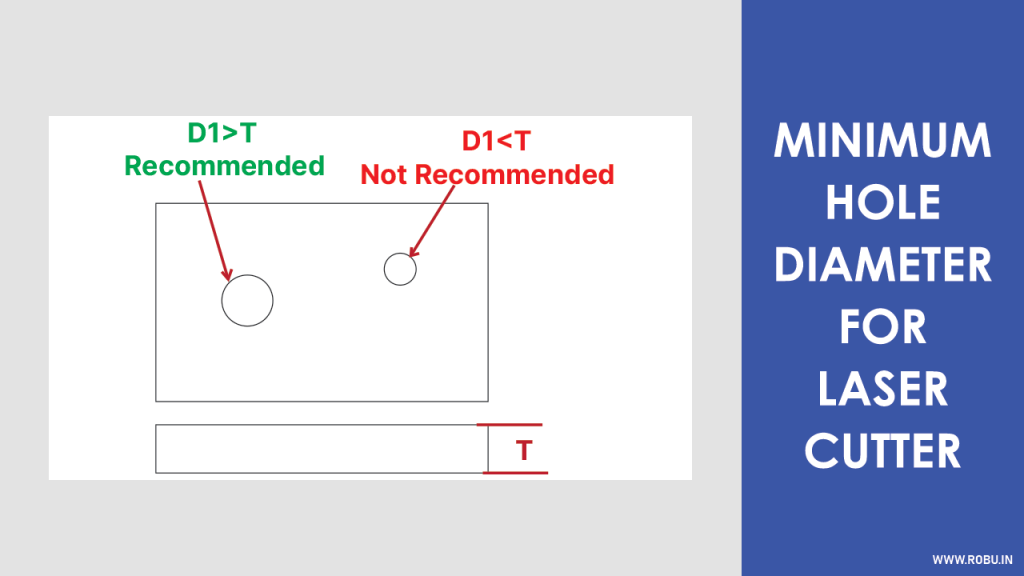
The holes cut or punched into the sheet metal should not be very small.
The diameter of the hole depends upon sheet metal thickness.
It is suggested that the diameter of the hole should be greater than 1 mm or equal to the thickness of the sheet metal, whichever is greater.
In the case of the Laser Cutting Machine, a high precision laser is needed to cut the small holes, so it is suggested to bind to the minimum hole diameter guidelines.
Notches
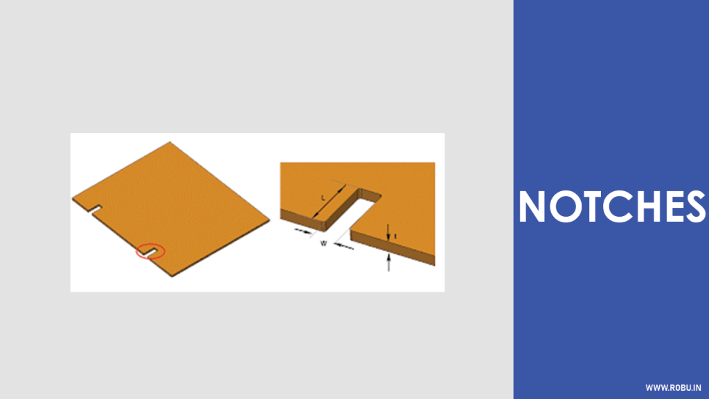
Notching is creating the intrusion or cutting the section of the sheet metal at the edges.
Guidelines for Cutting a Notch
Along with this, there are certain guidelines for notching as well,
- Notch Width ≥ (1.5 x Sheet Metal Thickness)
- Notch Length ≥ (5 x Sheet Metal Thickness)
- Distance between two adjacent notches ≥ (1.2 x Sheet Metal Thickness
- Corner Radius for Notch ≥ (0.5 x Sheet Metal Thickness)
Guidelines for Cutting the Notch near a bend
Cutting notches too close to the bend may distort the bend. The following formula is used to calculate the distance between the notch and bend.
Distance = 3 x Sheet Metal Thickness + Bend Radius
Consideration of all of the above guidelines is a must for successful notching and avoid future implications of poor design.
Corner Fillet (Edge Fillet)
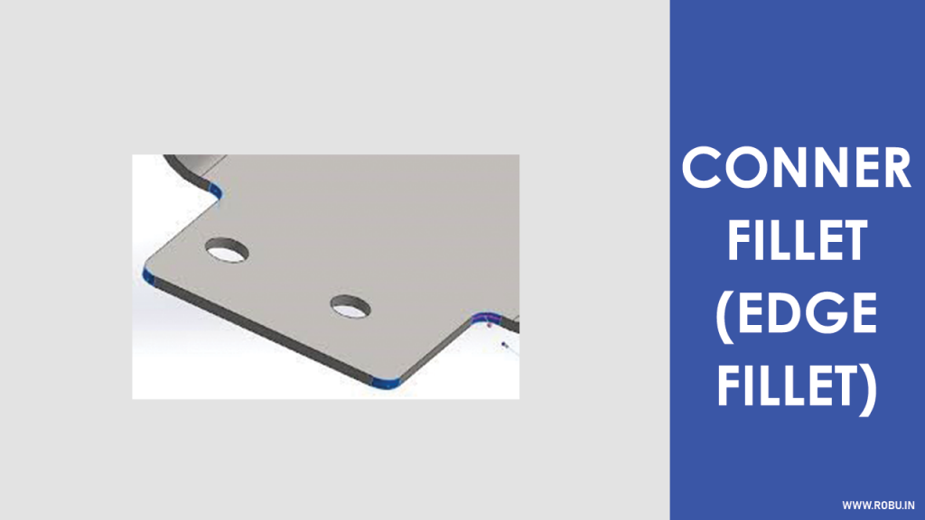
Sheet metals may have sharp corners that can damage other materials near them or humans handling them.
Edge or corner filleting is necessary for smoothing the sharp corners of the sheet metal.
It is the process of rounding the sharp edges of the sheet metal.
The purpose of this process is to make sheet metal handling safe and easier.
Generally, the corner fillet has dimensions equal to half of the thickness of the sheet metal.
Bending

The bending process is most common in sheet metal fabrication.
In this process, sheet metal is bent at the desired angle to form the final shape.
It uses the Press Braking Machine made up of two parts, a punch and a die. The workpiece is placed between these two parts.
The force applied by the punch and depth of the die decides the bending angle.
But before bending, you need to make sure that the force applied by the punch of Press Brake is greater than the yield strength of the sheet metal.
The process of bending is also known as flanging, folding and edging.
There are various types of bending used in fabrication,
- Air Bending
- V-Bending
- Step Bending
- U-Bending
- Roll Bending
- Wipe Bending
- Rotary Bending
Critical Dimensions for Bending
Understanding the terminologies used in the bending of sheet metal is very significant for every designer.
Let's discuss the things that you need to provide to CAD software while designing bend.
- Metal Thickness
- Bend Radius
- K-factor
1 Metal Thickness
Generally, the metal sheets used in the fabrication of industry-grade products have a thickness between 0.5 to 6 mm.
The thickness of sheet metal is very crucial while both designing and fabrication.
2 Bend Radius
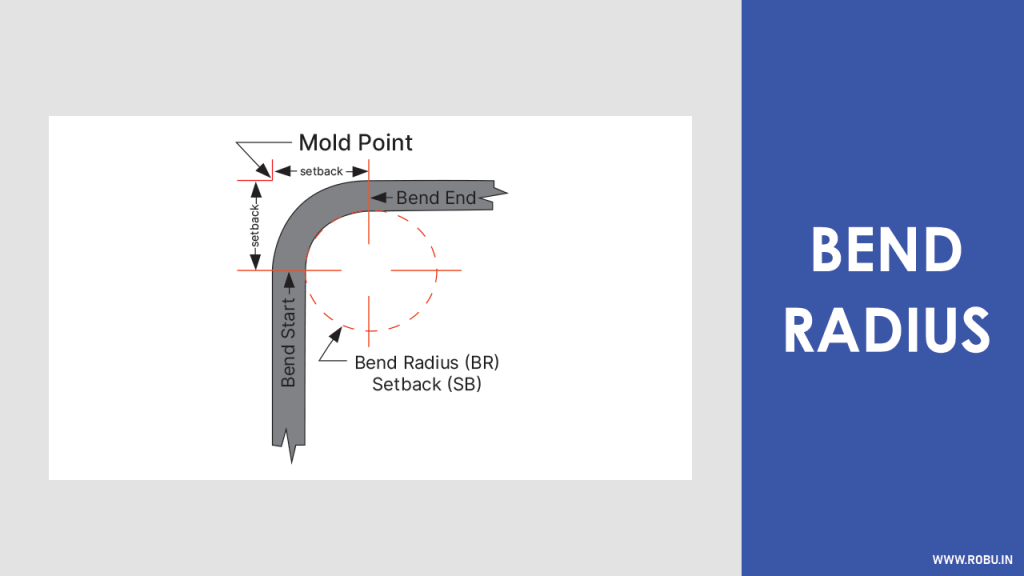
As shown in the above image, if we draw straight lines from the edges of the bend, then the distance from the intersection point of this line and the inner surface of the bend is known as the bend radius.
It is suggested to keep the bend radius uniform throughout the product's design for efficient and cost-effective fabrication.
We will discuss more about the design principles associated with Bend Radius in the next section.
To avoid the elastic restoration effect known as the Springback in the metal sheet, you need to over-bend the metal sheet to achieve the desired bend radius.
Sidenote: To know the impact of the elasticity effect, the ratio between the initial bend and final bend is measured, known as Springback Factor (SF).
3 Minimum Bend Radius (IR mm)
In the previous section, we talked about what is bend radius and its importance.
Now let's see what should be the minimum value of the bend radius for sheet metals to perform as per the requirements.
Successful bending of the sheet metal makes it stiffer than its flat counterparts.
Practically the bend radius varies according to the industry. E.g. In the case of the Aerospace industry, the bend radius is greater than the standard bend radius of the sheet metal of the same thickness.
Bend radius must be greater than 1 mm or equal to the thickness of the sheet, whichever is greater.
The Minimum Bend Radius Guidelines avoids fracturing and distortion of the sheet metal under design.
A greater amount of force is required in the case of thicker materials with smaller bend radii.
4 Minimum Flange Length (b mm)
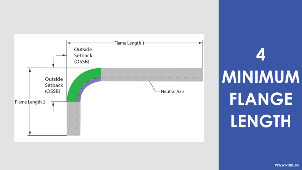
Flange Length is the distance between the exact middle of the bend and to the point where the bend ends.
This Flange Length of the corresponding bend must reach the top of the die where the bending process occurs.
You won't get the desired results with too short a flange length because the sheet metal would badly fall into the die.
Air Bend Force Chart is universally used to calculate the minimum flange length.
Measuring tonnage per meter is necessary for each fabrication.
The above chart demonstrates the tonnage required for bending sheet metals of various thickness.
The chart can be used for calculating bend radius and minimum flange length simultaneously.
Consider that we have a sheet metal of the thickness t = 3mm, and we are about to design the bend of radius ir = 3.3mm, then our minimum flange length will be b = 14mm.
5 Neutral Axis
While bending sheet metal, the outer surface of the bend will be stretched, and the inner surface of the bend undergoes compression.
The area or line where the transition from stretching to compression occurs is known as the Neutral Axis.
In contrast to the outer and inner axis of the bend that changes the length once the bend is formed, the neutral axis doesn't change the length because both compressions and extension are zero at this axis.
It is essential to know the location of the neutral axis to do the sheet metal calculations.
K-Factor calculates the location of the neutral axis. We will discuss it in the upcoming sections of this article.
6 Bend Allowance
When metals are bent, they change their dimensions.
Here the dimension changes can be noticed by looking at the outer surface of the bend, which would be elongated.
The elongation or increased length needs to be considered while developing a flat pattern from bend and vice versa.
Bend Allowance is defined as the added length to the sheet metal's leg to cut the flat pattern to the correct size.
As we discussed earlier, one side [outer] from the neutral axis stretches, and another side [inner] undergoes compression.
The following formula calculates bend allowance,
BA = [Bend Angle in Degree x (π/180)] x [Bend Radius + (K-Factor x Metal Thickness)]
Every parameter mentioned in the above formula is discussed earlier except the K-Factor, which we will discuss in the next section.
7 K-Factor
The K-Factor is the ratio of the distance of the neutral axis to the material thickness.
K = T/t
Where,
K = K-Factor
T = Distance of the neutral axis
t = Sheet Metal Thickness
It is mainly used to calculate the changes in the neutral axis's location in bend and how much material is stretched after bending.
The changes in the location of the neutral axis depend upon the sheet metal physical properties and thickness.
Usually, the ratio is greater than 0.25 and does not exceed the maximum value of 0.50.
K-Factor is measure using the following formula,
K = [(180 x Bend Allowance) / (π x Bend Angle x Sheet Metal Thickness)] – (Bend Radius – Sheet Metal Thickness)
Knowing K-Factor is very significant to designers because it acts as a base value for many calculations throughout the designing and fabrication of sheet metal.
8 Bend Relief
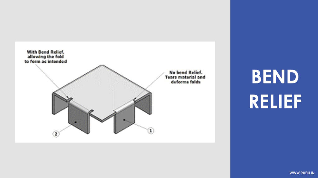
A Bend Relief avoids the sheet metal tearing if the bend is made at the edge of the material.
It is a cut along the sides of the bend. This cut creates free space between the bent and unbent surface of the sheet metal.
There are certain guidelines while giving or deciding this bend relief,
- The Bend Relief Depth must be greater than the bend radius
- The Bend Relief Width must be greater than or equal to the thickness of the sheet metal
You only bend relief if there's material on either side of the bend that you don't wish to bend or deform.
9 Bend Height
You need careful attention towards the bending height while designing because the poor bend height will lead to low quality bends that will fail in service.
Bend height is calculated using the following formula,
Bend Height (H) = 2 x Sheet Metal Thickness (t) + Bend Radius (ir)
To avoid the distortion of the bend, it is must to keep the bending height greater than twice the thickness of the sheet metal plus bend radius.
10 Bending Near Holes
If a bend is made too close to the hole, it may deform the hole. Refer to the following image,
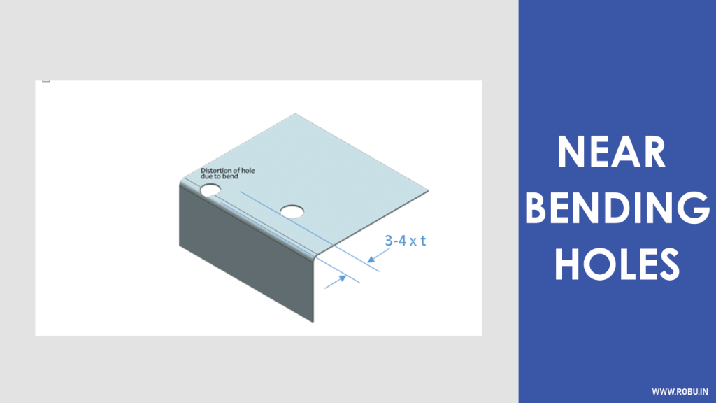
The following formula calculates the minimum distance from the bend at which you can punch or cut a hole,
Distance (D) = Sheet Metal Thickness (t) + Bend Radius (ir) + Diameter of The Hole
So, from the formula, it is clear that the distance is proportional to the sheet metal thickness, bend radius and diameter of the hole.
Conclusion
Following the design principles mentioned above will ensure that the final product will perform as per the requirements.
Note that the design guidelines explained in this article are generic and applies to all types of materials (sheet metals).
If you have any doubts, then don't forget to comment below.
Sheet metals durable and cost-effective that makes them popular. But before designing and fabrication, make sure that you strictly follow the guidelines and tolerances mentioned in this article.


