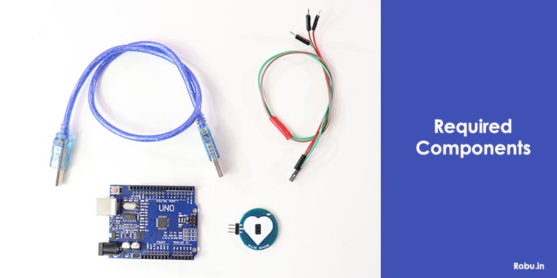
Pulse sensor detects pulse of a person. In this article, we will learn on which principle it works & how to interface it with Arduino.

Hello Again! Welcome to another blog on Robu.
In this modern world, where everyone needs more features and specifications on their hands. This sensor just became popular recently, once companies started implementing this in consumer electronics.
It is used in many devices right now such as smart bands, smartwatches, & medical equipment. Knowing the pulse rate/heart rate at the correct time can be crucial in saving someone's life.
In this blog, we will cover few parts of the pulse sensor, like some basic introduction to the sensor -what it is, how it works, its pinout, and connection with Arduino. Let's get into it. : )
What is Pulse Sensor?
Let's start from very basic, it is nothing but the same as other sensors. It detects data from the sensor and feeds the data to the controller. but every sensor feeds different information, some feed voltage, current, etc data, while this one feeds pulse information to the controller.
It detects how many pulses are going in a minute. For it, You just have to simply put your fingertip on the sensor.

Pulse sensors as said above are used in consumer electronics such as smartwatches and bands. Many brands/most of them have implemented this in their products, they provided an app that tracks the heart rate and other data continuously throughout the day, which helps in understanding the body.
For a normal person it is not that much of a necessity but let's say there are people who are very health cautious nowadays and athletes. They require this information to train their bodies in a better way.
Working of Pulse Sensor
The working principle on which the sensor works is pretty straight forward. Pulse sensor has two sides as you can see in the below image, looks similar to a coin. The first surface has a heart made on it. That side has the actual sensor mounted, which is actually an LED coupled with an ambient light sensor.

So when the light is emitted and the finger is put on it, the sensor will detect the flow of blood through the veins. With the flow of blood, the heart rate can be calculated easily. A small variation in light changes will be detected as blood will flow by the ambient light sensor.
The sensor is mounted on the side which has a heart drawn. The center has two dots which is the actual sensor combined with LED and ambient light sensors .
The other side has the actual circuit on which the sensor works, which you can see in the above image.
The function of the circuit here is to cancel the noise which might be there while sensing and to amplify the sensor data provided so that the controller can understand that data more clearly. The sensor actually provides data in analog format. So you can use the analog pins of the controller.
Pin-out and Connection with Arduino

In this section, we will be seeing the pin-outs and further will interface the sensor with the Arduino. We can also combine a display with it, to see the data. But I'm gonna keep it simple, we can see the data on the Serial Monitor, and the display connection is not big of a deal.
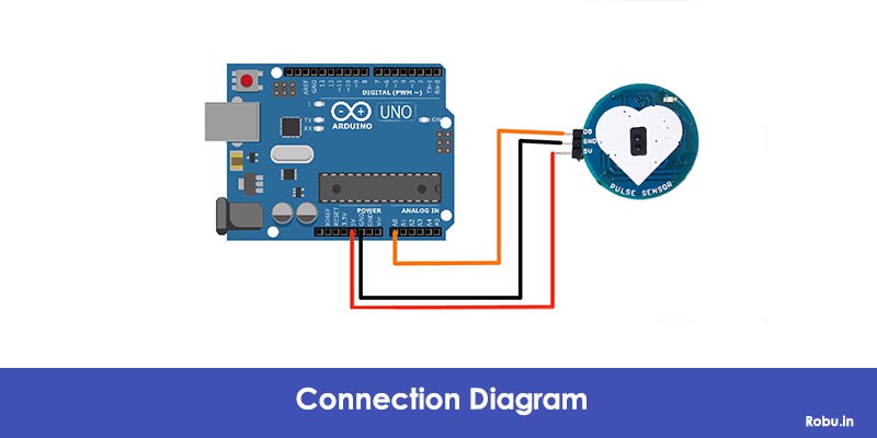
- The sensor has three pins here, mainly 5V, GND, and D0. Yours can be a bit different from us.

The sensor provides data on the D0 pin in analog form. You can connect 5V and GND. The sensor only consumes 4mA current. Our sensor also has an LED mounted on top separately to indicate the working.
Now we are going to connect it with the Arduino,
- We are going to connect the 5V pin to the 5V pin on the Arduino
- We are going to connect the ground to any of the grounds on the Arduino board.
- We are going to connect the D0 pin to the A0 of the Arduino, which will detect the analog signal given from the sensor.
- Now we will upload the below code, Explanation of the code is in the code itself.
Code
//www.robu.in
//  Variables
int pulsePin = 0;                 // Pulse Sensor purple wire connected to analog pin 0
int blinkPin = 13;                // pin to blink led at each beat
int fadePin = 8;                  // pin to do fancy classy fading blink at each beat
int fadeRate = 0;                 // used to fade LED on with PWM on fadePin


// Volatile Variables, used in the interrupt service routine!
volatile int BPM;                   // int that holds raw Analog in 0. updated every 2mS
volatile int Signal;                // holds the incoming raw data
volatile int IBI = 600;             // int that holds the time interval between beats! Must be seeded!
volatile boolean Pulse = false;     // "True" when User's live heartbeat is detected. "False" when not a "live beat".
volatile boolean QS = false;        // becomes true when Arduoino finds a beat.

// Regards Serial OutPut  -- Set This Up to your needs
static boolean serialVisual = true;   // Set to 'false' by Default.  Re-set to 'true' to see Arduino Serial Monitor ASCII Visual Pulse

volatile int rate[10];                      // array to hold last ten IBI values
volatile unsigned long sampleCounter = 0;          // used to determine pulse timing
volatile unsigned long lastBeatTime = 0;           // used to find IBI
volatile int P = 512;                      // used to find peak in pulse wave, seeded
volatile int T = 512;                     // used to find trough in pulse wave, seeded
volatile int thresh = 525;                // used to find instant moment of heart beat, seeded
volatile int amp = 100;                   // used to hold amplitude of pulse waveform, seeded
volatile boolean firstBeat = true;        // used to seed rate array so we startup with reasonable BPM
volatile boolean secondBeat = false;      // used to seed rate array so we startup with reasonable BPM

void setup()
{
  pinMode(blinkPin,OUTPUT);         // pin that will blink to your heartbeat!
  pinMode(fadePin,OUTPUT);          // pin that will fade to your heartbeat!
  Serial.begin(115200);             // we agree to talk fast!
  interruptSetup();                 // sets up to read Pulse Sensor signal every 2mS
                                    // IF YOU ARE POWERING The Pulse Sensor AT VOLTAGE LESS THAN THE BOARD VOLTAGE,
                                    // UN-COMMENT THE NEXT LINE AND APPLY THAT VOLTAGE TO THE A-REF PIN
                                    //   analogReference(EXTERNAL);
}


//  Where the Magic Happens
void loop()
{
   serialOutput();

  if (QS == true) // A Heartbeat Was Found
    {
      // BPM and IBI have been Determined
      // Quantified Self "QS" true when arduino finds a heartbeat
      fadeRate = 255; // Makes the LED Fade Effect Happen, Set 'fadeRate' Variable to 255 to fade LED with pulse
      serialOutputWhenBeatHappens(); // A Beat Happened, Output that to serial.
      QS = false; // reset the Quantified Self flag for next time
    }

  ledFadeToBeat(); // Makes the LED Fade Effect Happen
  delay(200); //  take a break
}

void ledFadeToBeat()
{
   fadeRate -= 15;                         //  set LED fade value
   fadeRate = constrain(fadeRate,0,255);   //  keep LED fade value from going into negative numbers!
   analogWrite(fadePin,fadeRate);          //  fade LED
}

void interruptSetup()
{
  // Initializes Timer2 to throw an interrupt every 2mS.
  TCCR2A = 0x02;     // DISABLE PWM ON DIGITAL PINS 3 AND 11, AND GO INTO CTC MODE
  TCCR2B = 0x06;     // DON'T FORCE COMPARE, 256 PRESCALER
  OCR2A = 0X7C;      // SET THE TOP OF THE COUNT TO 124 FOR 500Hz SAMPLE RATE
  TIMSK2 = 0x02;     // ENABLE INTERRUPT ON MATCH BETWEEN TIMER2 AND OCR2A
  sei();             // MAKE SURE GLOBAL INTERRUPTS ARE ENABLED
}

void serialOutput()
{   // Decide How To Output Serial.
 if (serialVisual == true)
  {
     arduinoSerialMonitorVisual('-', Signal);   // goes to function that makes Serial Monitor Visualizer
  }
 else
  {
      sendDataToSerial('S', Signal);     // goes to sendDataToSerial function
   }
}

void serialOutputWhenBeatHappens()
{
 if (serialVisual == true) //  Code to Make the Serial Monitor Visualizer Work
   {
     Serial.print("<<<Robu Heart-Beat Sensor-- >>> ");  //ASCII Art Madness
     Serial.print("BPM: ");
     Serial.println(BPM);

   }
 else
   {
     sendDataToSerial('B',BPM);   // send heart rate with a 'B' prefix
     sendDataToSerial('Q',IBI);   // send time between beats with a 'Q' prefix
   }
}

void arduinoSerialMonitorVisual(char symbol, int data )
{
  const int sensorMin = 0;      // sensor minimum, discovered through experiment
  const int sensorMax = 1024;    // sensor maximum, discovered through experiment
  int sensorReading = data; // map the sensor range to a range of 12 options:
  int range = map(sensorReading, sensorMin, sensorMax, 0, 11);
  // do something different depending on the
  // range value:
  switch (range)
  {
    case 0:
      Serial.println("");     /////ASCII Art Madness
      break;
    case 1:
      Serial.println("---");
      break;
    case 2:
      Serial.println("------");
      break;
    case 3:
      Serial.println("---------");
      break;
    case 4:
      Serial.println("------------");
      break;
    case 5:
      Serial.println("--------------|-");
      break;
    case 6:
      Serial.println("--------------|---");
      break;
    case 7:
      Serial.println("--------------|-------");
      break;
    case 8:
      Serial.println("--------------|----------");
      break;
    case 9:
      Serial.println("--------------|----------------");
      break;
    case 10:
      Serial.println("--------------|-------------------");
      break;
    case 11:
      Serial.println("--------------|-----------------------");
      break;
  }
}


void sendDataToSerial(char symbol, int data )
{
   Serial.print(symbol);
   Serial.println(data);
}

ISR(TIMER2_COMPA_vect) //triggered when Timer2 counts to 124
{
  cli();                                      // disable interrupts while we do this
  Signal = analogRead(pulsePin);              // read the Pulse Sensor
  sampleCounter += 2;                         // keep track of the time in mS with this variable
  int N = sampleCounter - lastBeatTime;       // monitor the time since the last beat to avoid noise
                                              //  find the peak and trough of the pulse wave
  if(Signal < thresh && N > (IBI/5)*3) // avoid dichrotic noise by waiting 3/5 of last IBI
    {
      if (Signal < T) // T is the trough
      {
        T = Signal; // keep track of lowest point in pulse wave
      }
    }

  if(Signal > thresh && Signal > P)
    {          // thresh condition helps avoid noise
      P = Signal;                             // P is the peak
    }                                        // keep track of highest point in pulse wave

  //  NOW IT'S TIME TO LOOK FOR THE HEART BEAT
  // signal surges up in value every time there is a pulse
  if (N > 250)
  {                                   // avoid high frequency noise
    if ( (Signal > thresh) && (Pulse == false) && (N > (IBI/5)*3) )
      {
        Pulse = true;                               // set the Pulse flag when we think there is a pulse
        digitalWrite(blinkPin,HIGH);                // turn on pin 13 LED
        IBI = sampleCounter - lastBeatTime;         // measure time between beats in mS
        lastBeatTime = sampleCounter;               // keep track of time for next pulse

        if(secondBeat)
        {                        // if this is the second beat, if secondBeat == TRUE
          secondBeat = false;                  // clear secondBeat flag
          for(int i=0; i<=9; i++) // seed the running total to get a realisitic BPM at startup
          {
            rate[i] = IBI;
          }
        }

        if(firstBeat) // if it's the first time we found a beat, if firstBeat == TRUE
        {
          firstBeat = false;                   // clear firstBeat flag
          secondBeat = true;                   // set the second beat flag
          sei();                               // enable interrupts again
          return;                              // IBI value is unreliable so discard it
        }
      // keep a running total of the last 10 IBI values
      word runningTotal = 0;                  // clear the runningTotal variable

      for(int i=0; i<=8; i++)
        {                // shift data in the rate array
          rate[i] = rate[i+1];                  // and drop the oldest IBI value
          runningTotal += rate[i];              // add up the 9 oldest IBI values
        }

      rate[9] = IBI;                          // add the latest IBI to the rate array
      runningTotal += rate[9];                // add the latest IBI to runningTotal
      runningTotal /= 10;                     // average the last 10 IBI values
      BPM = 60000/runningTotal;               // how many beats can fit into a minute? that's BPM!
      QS = true;                              // set Quantified Self flag
      // QS FLAG IS NOT CLEARED INSIDE THIS ISR
    }
  }

  if (Signal < thresh && Pulse == true)
    {   // when the values are going down, the beat is over
      digitalWrite(blinkPin,LOW);            // turn off pin 13 LED
      Pulse = false;                         // reset the Pulse flag so we can do it again
      amp = P - T;                           // get amplitude of the pulse wave
      thresh = amp/2 + T;                    // set thresh at 50% of the amplitude
      P = thresh;                            // reset these for next time
      T = thresh;
    }

  if (N > 2500)
    {                           // if 2.5 seconds go by without a beat
      thresh = 512;                          // set thresh default
      P = 512;                               // set P default
      T = 512;                               // set T default
      lastBeatTime = sampleCounter;          // bring the lastBeatTime up to date
      firstBeat = true;                      // set these to avoid noise
      secondBeat = false;                    // when we get the heartbeat back
    }

  sei();                                   // enable interrupts when youre done!
}// end isr
Final Words
So in this blog, we learned a few things about pulse sensors. It is actually combined with two sensors LED and an ambient light sensor. We saw how it can help us improve and monitor our health.
It can also be used in medical applications to detect heart rate. we interfaced it with an Arduino Uno board. We also checked pinouts and then heart rates by writing the code, to see the practical working of the sensor.
Let me know your thoughts on this in the comment section, share it if you found the information useful. Sayonara!
Until Next Time!!!


