Introduction To Buck-Boost Converter
This guide covers what is buck-boost converter, operating principle, and its applications.

Hello guys, Today in this session we are going to see the introduction of the Buck-boost converter. Buck-boost converters are a form of switching-mode power supply. It can supply a regulated DC output from a source voltage either above or below the desired output voltage. This can be particularly helpful in battery-powered applications in which the battery voltage starts out above the desired output but falls below as the battery drains. It’s useful for every engineer to understand the fundamentals of buck-boost converters.
Introduction
The Buck–boost converter is a type of DC-to-DC converter that has an output voltage magnitude that is either greater than or less than the input voltage magnitude. It is equivalent to a Fly-back converter using a single inductor instead of a transformer.
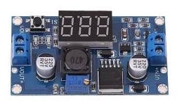
[caption id="attachment_756610" align="aligncenter" width="525"] Buck-Boost converter[/caption]
In the other words we can also say that, a Buck-boost converter steps a voltage up or down, producing a voltage equal to or higher or lower than the input voltage. A buck boost could be used to provide a 12 V output from a 12 V battery. A 12 V battery’s voltage can vary between 10 V and 14.7 V. A buck boost could also power an LED from a single cell.
Application of this module
Normally we look for application at last, but according to me we should mention its application first, to know why we are using Buck-Boost Conveter,
Here following are some examples of Buck-Boost converter:
- Battery Charger/USB Charging Ports in Portable Devices: Everyone wants their smartphone, tablet, or portable battery pack to charge quickly without heating up their portable devices. A synchronous BUCK converter can be used for this application. Typically, a charging port for a mobile device is a micro USB port. It accepts a regulated 5 V. The charging circuits are on the inside of the mobile device, which is often a BUCK converter.
- AMOLED (Active Matrix OLED) Displays in Wearable Devices: Powering AMOLED displays in wearable devices requires DC-DC switching converters that offer high power efficiency and tight output voltage accuracy.
- DDR-SDRAM Memory: DDR-SDRAM memory requires DC-DC switching converters with tight accuracy requirements and ability to support fast load transients.
- Energy Harvesting Systems: High efficiency switching converters are a vital block in energy harvesting systems. It is the most adequate voltage regulation method in such low power systems. Boost converters with clock-controlled input impedance are used for MPPT (Maximum Power Point Tracking) operation.
- DVFS (Dynamic Voltage Frequency Scaling): Performance-Power tradeoff in microprocessors and digital signal processing circuits is managed using switching converters. Increasing the digital circuit supply leads to increasing the performance (speed) at the expense of dynamic power consumption and vice versa.
Operating Principle of Buck Boost Converter
The main element of this circuit is:
- solid state device(Swtich or MOSFET)
- Inductor
- Diode(act as a switch)
- capacitor
- DC voltage source
The input voltage source is connected to a solid state device. The second switch used is a diode. The diode is connected, in reverse to the direction of power flow from source, to a capacitor and the load and the two are connected in parallel as shown in the figure below,
[caption id="attachment_756590" align="aligncenter" width="552"]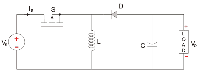 Circuit Diagram[/caption]
The controlled switch is turned on and off by using Pulse Width Modulation(PWM). PWM can be time based or frequency based. Frequency based modulation has disadvantages like a wide range of frequencies to achieve the desired control of the switch which in turn will give the desired output voltage. Time based Modulation is mostly used for DC-DC converters. It is simple to construct and use. The frequency remains constant in this type of PWM modulation.
The Buck Boost converter works two modes of operation. The first mode is when the switch is on and conducting.
Mode I : Switch is ON, Diode is OFF
[caption id="attachment_756626" align="aligncenter" width="575"]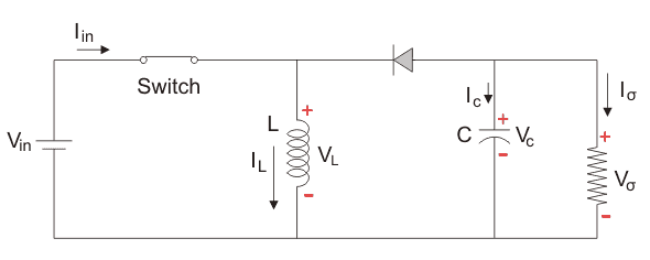 Mode-I[/caption]
In this case, when the switch is closed, the inductor starts charging, due to closing of switch the circuit offers zero resistance to the flow of current and inductor starts cherging,and charges upto its peak level.
The inductor stores the charge when the switch is in on the condition and when the switch goes into its off state, charge across inductor gets reverse and it flows through the load and through the diode and back to the inductor, So the direction of current through the inductor remains the same.
Let us say the switch is on for a time TON and is off for a time TOFF. We define the time period, T, as T = TON + TOFF and the switching frequency,
FSWITCHING = 1 ÷ T
Duty Cycle can be calculated as, ![]()
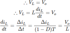
from derivation we can calculate voltage across inductor,
TON = DT , we can say that Δt = DT
We know that D varies between 0 and 1. If D > 0.5, the output voltage is larger than the input; and if D < 0.5, the output is smaller than the input. But if D = 0.5 the output voltage is equal to the input voltage.
While performing the analysis of the Buck-Boost converter we have to keep in mind that
- The inductor current is continuous and this is made possible by selecting an appropriate value of L.
- The inductor current in steady-state rises from a value with a positive slope to a maximum value during the ON state and then drops back down to the initial value with a negative slope. Therefore the net change of the inductor current over any one complete cycle is zero.
Mode II: Switch is OFF, Diode is ON
[caption id="attachment_758676" align="aligncenter" width="590"]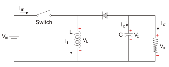 Mode-II[/caption]
In this mode, a switch is open make inductor reverse its polarity and start discharging and is ultimately dissipated in the load resistance and this helps to maintain the flow of current in the same direction through the load and also step-up the output Voltage as the inductor is now also acting as a source in conjunction with the input source.
By applying KVL in this mode II we get the following results,
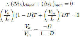
Since the switch is open for a time ![]() we can say that
we can say that ![]()
It is already established that the net change of the inductor current over any one complete cycle is zero.
We know that the Duty cycle(D) varies between 0 and 1. If D > 0.5, the output voltage is larger than the input; and if D < 0.5, the output is smaller than the input. But if D = 0.5 the output voltage is equal to the input voltage.
So from this above analysis, we conclude that lowering and boosting power of output voltage depends upon the duty cycle of the switch.
The controlled switch is turned on and off by using Pulse Width Modulation(PWM). PWM can be time-based or frequency-based. Time-based Modulation is mostly used for DC-DC Converter. It is simple to construct and use. The frequency remains constant in this type of PWM modulation.
Selection Procedure of Buck-Boost Converter
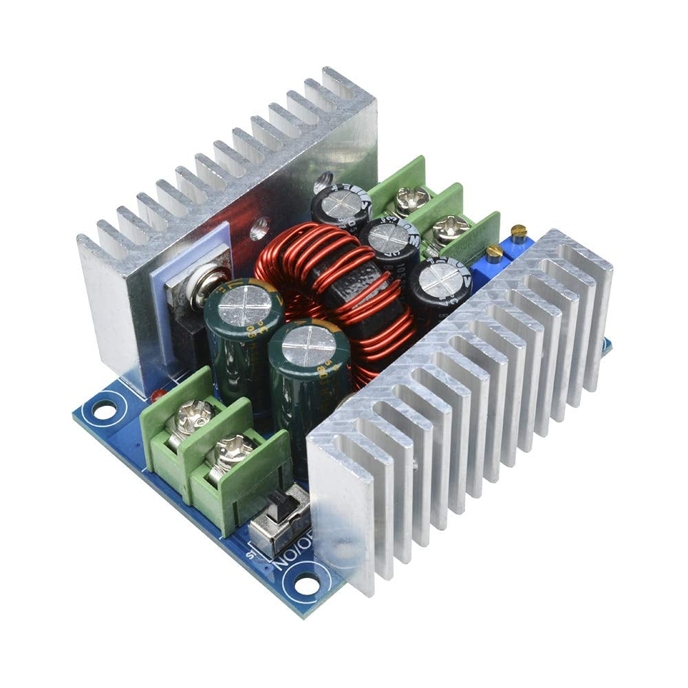
[caption id="attachment_407015" align="alignnone" width="295"]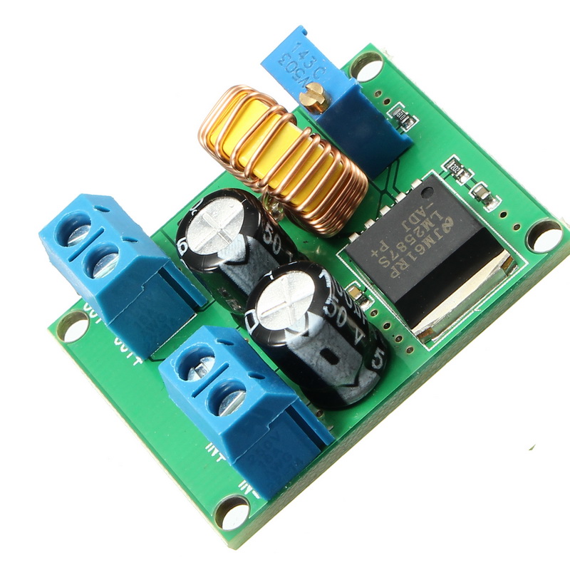 DC-DC Power Converter[/caption]
When you are going to buy Buck-Boost converter into maket, you should keep some points in mind which are :
- Select a group of converters that meet the basic parameters for your application. For example, what is the required input voltage and output voltage range? Do you require input-output isolation? What is the maximum current requirement?
- Arrange the parameters of the performance column of Table 1 in priority order based on the importance to your application. Then, from the group of converters chosen in Step #1, choose the converters that meet these arranged parameters in the specified order.
- In this step, narrow your selection to the one performance parameter that is most important for your application.
- Study the practical aspects mentioned above in detail to help in your converter selection.
- Now that you have made your converter selection, find out which optional parameters the converter offers for your application.
Conclusion
Today’s complex systems continue to add more and more functions that require multiple supply voltage levels. We can use DC-DC switching converters in multiple applications. With this simple procedure and parameter/application reference, system designers can select the best switching converter for any application.
I hope you find above information about basics of BUCK-BOOST conveter useful. To get more efficient buck boost module you can check here
If you have any doubt please let us know in the comment section below


