Servo Motor Working Principle
Here’s an article that explains how a Servo Motor works? and How it is controlled?

Have you ever thought about how a robotic vehicle commonly uses in military application to control bomb detention. Also, how metal cutting and forming machines provide precise motion for milling, lathes and bending for metal fabrication. And how an antenna positioning system control the precision in azimuth and elevation?
In all these application, servo motor is used and in this article, we are going to learn about the working principle of servo motor.
MUST READ BLOG POSTS ON SERVO MOTOR:
- What is servo motor?
- Servo Motor Working Principle
- Interfacing servo motor using Arduino
- What are the types of servo motor?
Working Principle of Servo Motor
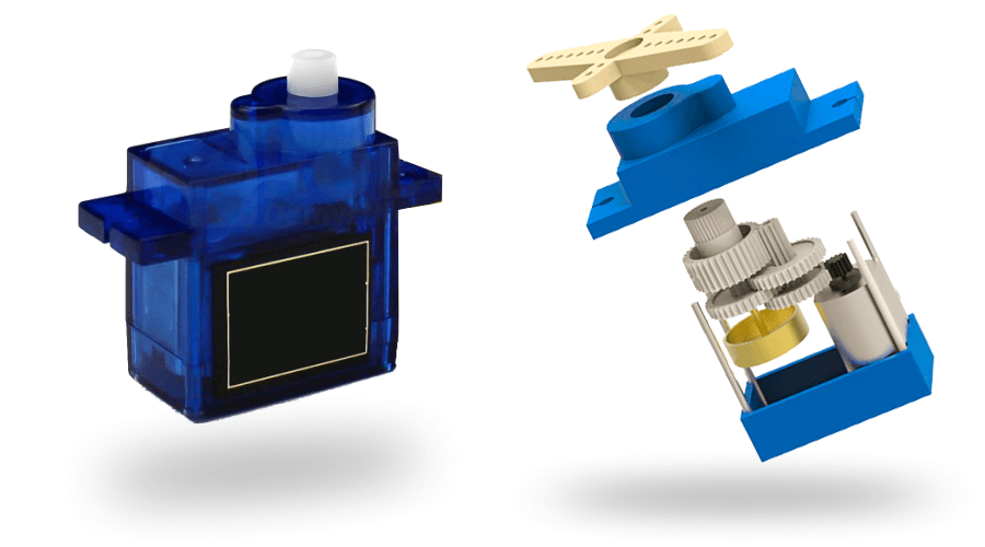
A DC servo motor is an assembly of four major components,
- DC motor
- Position sensing device
- Gear assembly
- Control circuit
In digital control, micro controller used for generating the PWM pluses in terms of duty cycles to produce more accurate control signals.
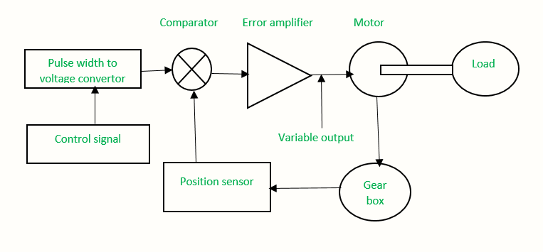
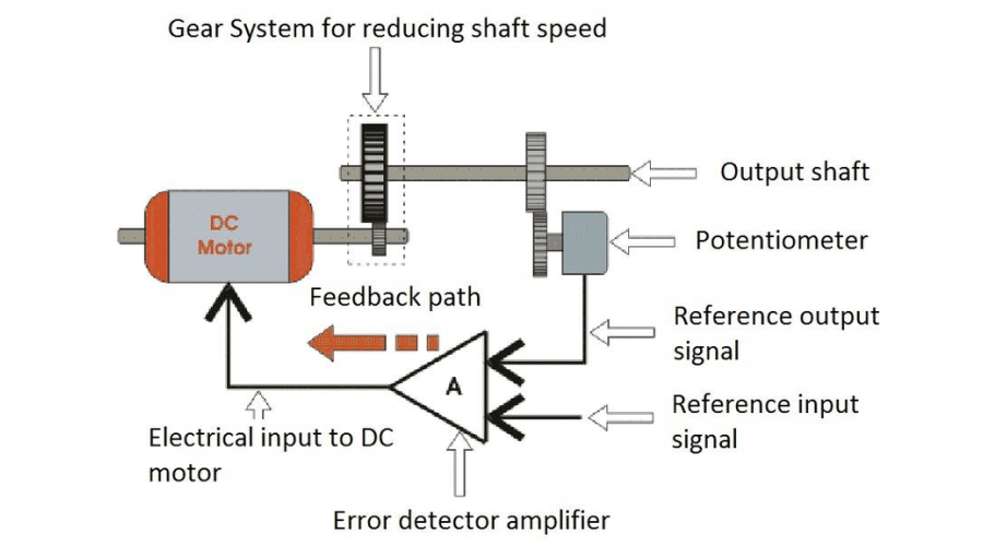
The position sensor provide a feedback signal corresponding to the present position of the load. This sensor is normally a potentiometer that produces the voltage corresponding to the absolute angle of the motor shaft through gear mechanism. Then the feedback voltage value applies on the input of error amplifier.
The error amplifier is a negative feedback amplifier and it reduces the difference between its inputs. It compares the voltage related to current position of the motor with desired voltage related to desired position of the motor. And it produces the error either a positive or negative voltage.
This error voltage applied to the armature of the motor. If the error is more then motor armature gets more output.
The amplifier amplifies the error voltage and powers the armature. The motor rotates till the error becomes zero. If the error is negative, the armature voltage reverses and hence the armature rotates in the opposite direction.
How to control servo?
The below figure shows the parts that consisting in RC servo motors in which small DC motor employees for driving the loads at precise speed and position.
The pulse width determines the angular position of the servo motor. In some circuits, a control pulse uses to produce DC reference voltage corresponding to desired position or speed of the motor. And it applies to a pulse width to voltage converter.
In this converter, the capacitor starts charging at a constant rate when the pulse is high. when the pulse is low, the charge on the capacitor fed to the buffer amplifier. So the length of the pulse decides the voltage applied at the error amplifier as a desired voltage to produce the desired speed or position.
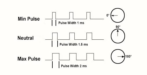
For example, a 1.5ms pulse will make the motor turn to the 90° position. Shorter than 1.5ms moves it in the counter clockwise direction toward the 0° position. Any longer than 1.5ms will turn the servo in a clockwise direction toward the 180° position.
Servos are controlled by sending an electrical pulse of variable width, or pulse width modulation (PWM), There is a minimum pulse, a maximum pulse, and a repetition rate. A servo motor can usually only turn 90° in either direction for a total of 180° movement. The motor's neutral position is defined as the position where the servo has the same amount of potential rotation in the both the clockwise or counter-clockwise direction.
As per the command, servo will move to the position and hold that position. The maximum amount of force the servo can exert is called the torque rating of the servo. Servos will not hold their position forever. Though, the position pulse must be repeated to instruct the servo to stay in position.


